
Turn on suggestions
Auto-suggest helps you quickly narrow down your search results by suggesting possible matches as you type.
Showing results for
Turn on suggestions
Auto-suggest helps you quickly narrow down your search results by suggesting possible matches as you type.
Showing results for
Community Tip - Learn all about the Community Ranking System, a fun gamification element of the PTC Community. X
- Community
- Creo+ and Creo Parametric
- 3D Part & Assembly Design
- Re: Pro/Sheetmetal Bend Question
Options
- Subscribe to RSS Feed
- Mark Topic as New
- Mark Topic as Read
- Float this Topic for Current User
- Bookmark
- Subscribe
- Mute
- Printer Friendly Page
Pro/Sheetmetal Bend Question
May 13, 2013
01:06 PM
- Mark as New
- Bookmark
- Subscribe
- Mute
- Subscribe to RSS Feed
- Permalink
- Notify Moderator
May 13, 2013
01:06 PM
Pro/Sheetmetal Bend Question
Hi I am trying to make the attached picture out of angle iron in pro sheetmetal. I can get the first basic wall, and bend and unbend it, but I cannot add the pattern shown. It makes a "C" shape. Anyone have any input?
This thread is inactive and closed by the PTC Community Management Team. If you would like to provide a reply and re-open this thread, please notify the moderator and reference the thread. You may also use "Start a topic" button to ask a new question. Please be sure to include what version of the PTC product you are using so another community member knowledgeable about your version may be able to assist.
11 REPLIES 11
May 13, 2013
01:14 PM
- Mark as New
- Bookmark
- Subscribe
- Mute
- Subscribe to RSS Feed
- Permalink
- Notify Moderator
May 13, 2013
01:14 PM
What do you mean the pattern makes a C shape?
May 13, 2013
01:16 PM
- Mark as New
- Bookmark
- Subscribe
- Mute
- Subscribe to RSS Feed
- Permalink
- Notify Moderator
May 13, 2013
01:16 PM
When the 45 degree notches are punched out of the angle iron the shape of the final object would be a "C".
May 13, 2013
01:31 PM
- Mark as New
- Bookmark
- Subscribe
- Mute
- Subscribe to RSS Feed
- Permalink
- Notify Moderator
May 13, 2013
01:31 PM
So the picture isn't the final shape? I'm guessing the final shape is taking that image and bending it at each notch to create a C. Are you trying to start with this and bend it to the final? Typically it's better to model the final shape rather than model the unbent and bend it.
That shape shouldn't be difficult, assuming I understand it correctly. I guess I'm confused at where you are having trouble. Perhaps opost a model or an image of what you are trying to create.
May 13, 2013
01:39 PM
- Mark as New
- Bookmark
- Subscribe
- Mute
- Subscribe to RSS Feed
- Permalink
- Notify Moderator
May 13, 2013
01:39 PM
Doug, I attached an igs. of what i am trying to do.
Lets call wall "A" the wall that is bent, and wall "B" is the wall that has the notches in it.
I started off with wall "A" in the bent configuration, and am able to do do my unbend and bend functions.
I am adding flats off of the bends, and have successfully been able to add one flat into the geometry that will correctly unbend/ bend
May 13, 2013
01:42 PM
- Mark as New
- Bookmark
- Subscribe
- Mute
- Subscribe to RSS Feed
- Permalink
- Notify Moderator
May 13, 2013
01:42 PM
It seems like I am doing this correctly now, if there is a 1/16" gap inbetween the corner and the flat it will happily accept this configuration.
Jan 14, 2014
05:54 PM
- Mark as New
- Bookmark
- Subscribe
- Mute
- Subscribe to RSS Feed
- Permalink
- Notify Moderator
Jan 14, 2014
05:54 PM
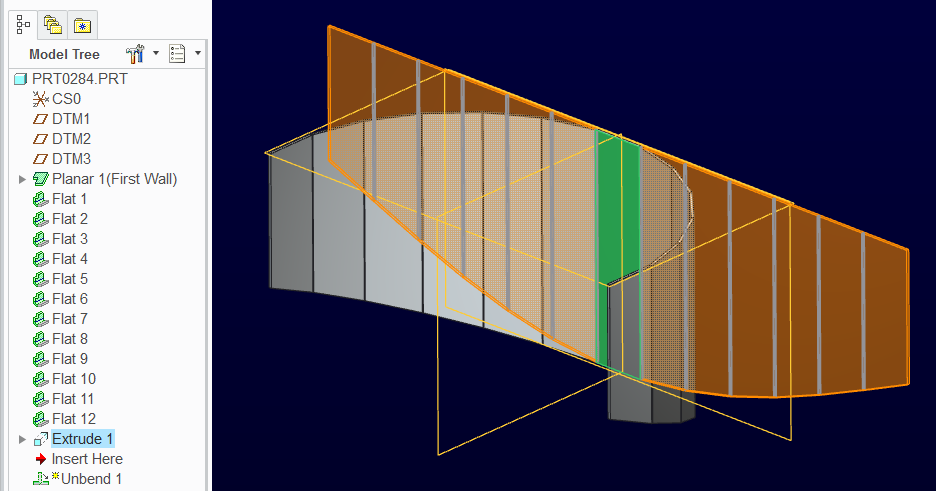
Hi, All.
I'm using Creo Wildfire 5
I've had much the same problem as was described in this post. Mine is a sheetmetal blend created between two sketches. I can't even create edge bends, which leads me to believe I did something very wrong. The steps I took are as follows:
Insert
Unattached
Blend
Then, once in the blend options:
General
Select Sketch
Straight
Chain Selection of two curves (my two sketches)
Material Direction Out
Attached is a picture of the part.

Thanks, Jonathon Kilihoffer
Jan 14, 2014
06:54 PM
- Mark as New
- Bookmark
- Subscribe
- Mute
- Subscribe to RSS Feed
- Permalink
- Notify Moderator
Jan 14, 2014
06:54 PM
Sheetmetal is a strange application when it comes to non-traditional shapes. It can do a lot but that 1st feature is key to successful follow on features. It looks like you are merge a representation of an arc to an ellipse on parallel planes. You might have to come at this in a much more complex manner if you want it to recognize an upbend or flat pattern feature.
Jan 15, 2014
08:14 AM
- Mark as New
- Bookmark
- Subscribe
- Mute
- Subscribe to RSS Feed
- Permalink
- Notify Moderator
Jan 15, 2014
08:14 AM
Hi, Antonius.
You're right. More specifically it is an arc made up of 13 flat sides merged to an elipse of an equal number (13) sides. I'm going to poke around at it some more. What is the more complex procedure that you were thinking of?
Thanks,
Jonathon Kilhoffer
Jan 15, 2014
08:55 AM
- Mark as New
- Bookmark
- Subscribe
- Mute
- Subscribe to RSS Feed
- Permalink
- Notify Moderator
Jan 15, 2014
08:55 AM
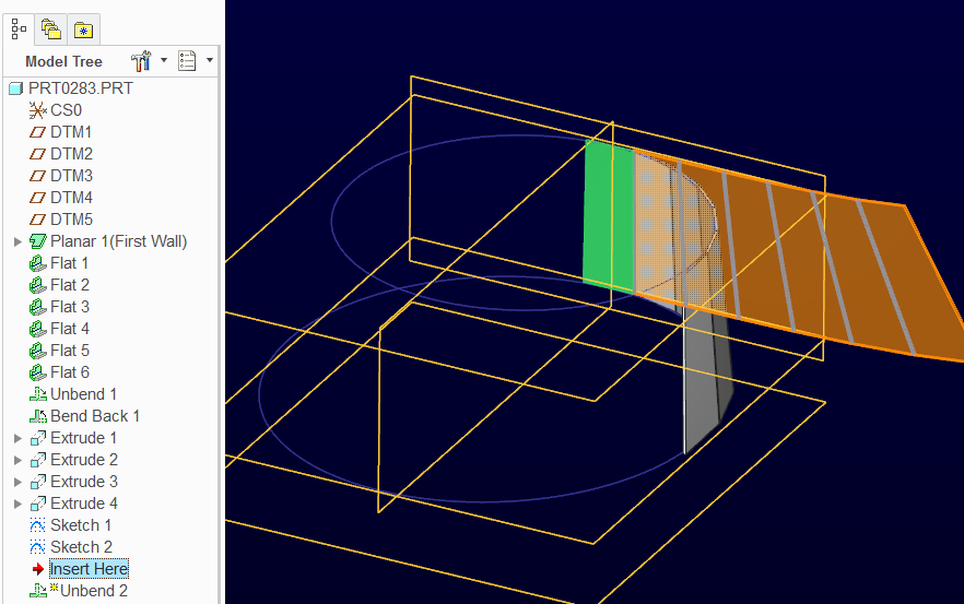
So I figured out what was causing my misery in this case. I think it was two things and I'll put the most straight-forward one first.
As soon as I made the sides parallel, it worked. My co-worker suggested that the shape may have been warping because some sides were twisting in while other where twisting out. He beleived that since this isn't realistic for real sheetmetal, that Pro didn't like it either.
Of course, I had made the sides parallel at a different time, when I was merging the top sketch to a non-parallel plane. However, in this case (as I saw from a previous post on some forum) this made it so that the edges were all diagonal (which sheetmetal usually doesn't like) Pro couldn't unbend it. So I extended out to a parallel plane and cut along the diagonal I wanted. The thing that makes this a headache is figuring out where things are supposed to go past that diagonal cutting plane (and that was a whole different trial that I will not write about in this post).
So to summarize:
Parallel sides.
Diagonal cut made after extending to parallel plane.
Thanks, Antonius, for your post. I've attached a picture of the finisthed geometry and its unbent state.


Jonathon Kilhoffer
Jan 15, 2014
02:00 PM
- Mark as New
- Bookmark
- Subscribe
- Mute
- Subscribe to RSS Feed
- Permalink
- Notify Moderator
Jan 15, 2014
02:00 PM
I was thinking to start with a small 1st surface and adding walls to it using the sketched shapes. "Unbend" the feature and trim the shape, and "Bend Back".
For the sketched wall, you can re-use the same sketch for each segment.
Technically, this is a very common practice in sheet metal. A series of breaks to simulate a rounded body or even make a square to round transition. It really should be a lot easier in Pro|E.
Jan 15, 2014
03:58 PM
- Mark as New
- Bookmark
- Subscribe
- Mute
- Subscribe to RSS Feed
- Permalink
- Notify Moderator
Jan 15, 2014
03:58 PM
This is what I was thinking. It does have some real challenges in working out the math to fit a certain shape.
But mine are parallel planes and it looks like yours are not. Now seeing the flat edge on your unfolded version makes that clear.
In that case, you just make all the walls the same length and extrude w/ remove material the angle on the lower edge.
