
Turn on suggestions
Auto-suggest helps you quickly narrow down your search results by suggesting possible matches as you type.
Showing results for
Turn on suggestions
Auto-suggest helps you quickly narrow down your search results by suggesting possible matches as you type.
Showing results for
Community Tip - When posting, your subject should be specific and summarize your question. Here are some additional tips on asking a great question. X
- Community
- Creo+ and Creo Parametric
- 3D Part & Assembly Design
- Rotation is discontinuous in beam idealization
Options
- Subscribe to RSS Feed
- Mark Topic as New
- Mark Topic as Read
- Float this Topic for Current User
- Bookmark
- Subscribe
- Mute
- Printer Friendly Page
Rotation is discontinuous in beam idealization
Nov 26, 2015
06:18 AM
- Mark as New
- Bookmark
- Subscribe
- Mute
- Subscribe to RSS Feed
- Permalink
- Notify Moderator
Nov 26, 2015
06:18 AM
Rotation is discontinuous in beam idealization
Hello,
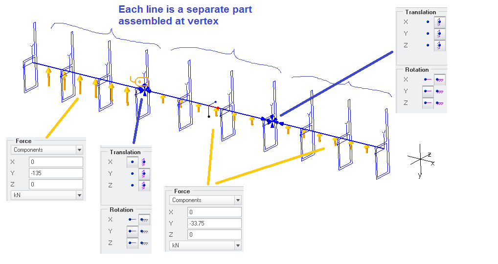
I am running an analysis on an idealized beam. This is basically a beam with 4 vertical displacement constraints.
As I need to have different load on the different segments (i.e. between different constraints), I have created it with three separate parts, each made of one sketched line
I have then put an idealized beam on the lines and placed the constraints at the vertexes and the loads on the edges.
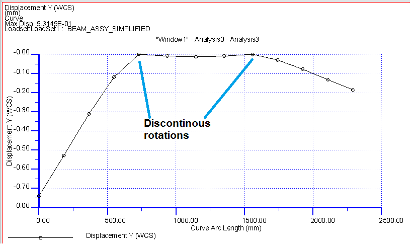
My problem is that I find expected moment and stresses, but the displacements don't seem to be OK. In particular, there is discontinuity of rotation at the joint between the parts. As the moment seem to be correctly transmitted, I don't understand this. Does anybody know what kind of precautions would be needed?
Alternatively, I wanted to use a single part and single line, but I am not able to assign a load only to a part of the line. Does anybody know how to do a region on a line?
Thanks
Massimo
This thread is inactive and closed by the PTC Community Management Team. If you would like to provide a reply and re-open this thread, please notify the moderator and reference the thread. You may also use "Start a topic" button to ask a new question. Please be sure to include what version of the PTC product you are using so another community member knowledgeable about your version may be able to assist.
Labels:
- Labels:
-
General
2 REPLIES 2
Dec 01, 2015
10:28 AM
- Mark as New
- Bookmark
- Subscribe
- Mute
- Subscribe to RSS Feed
- Permalink
- Notify Moderator
Dec 01, 2015
10:28 AM
Massimo,
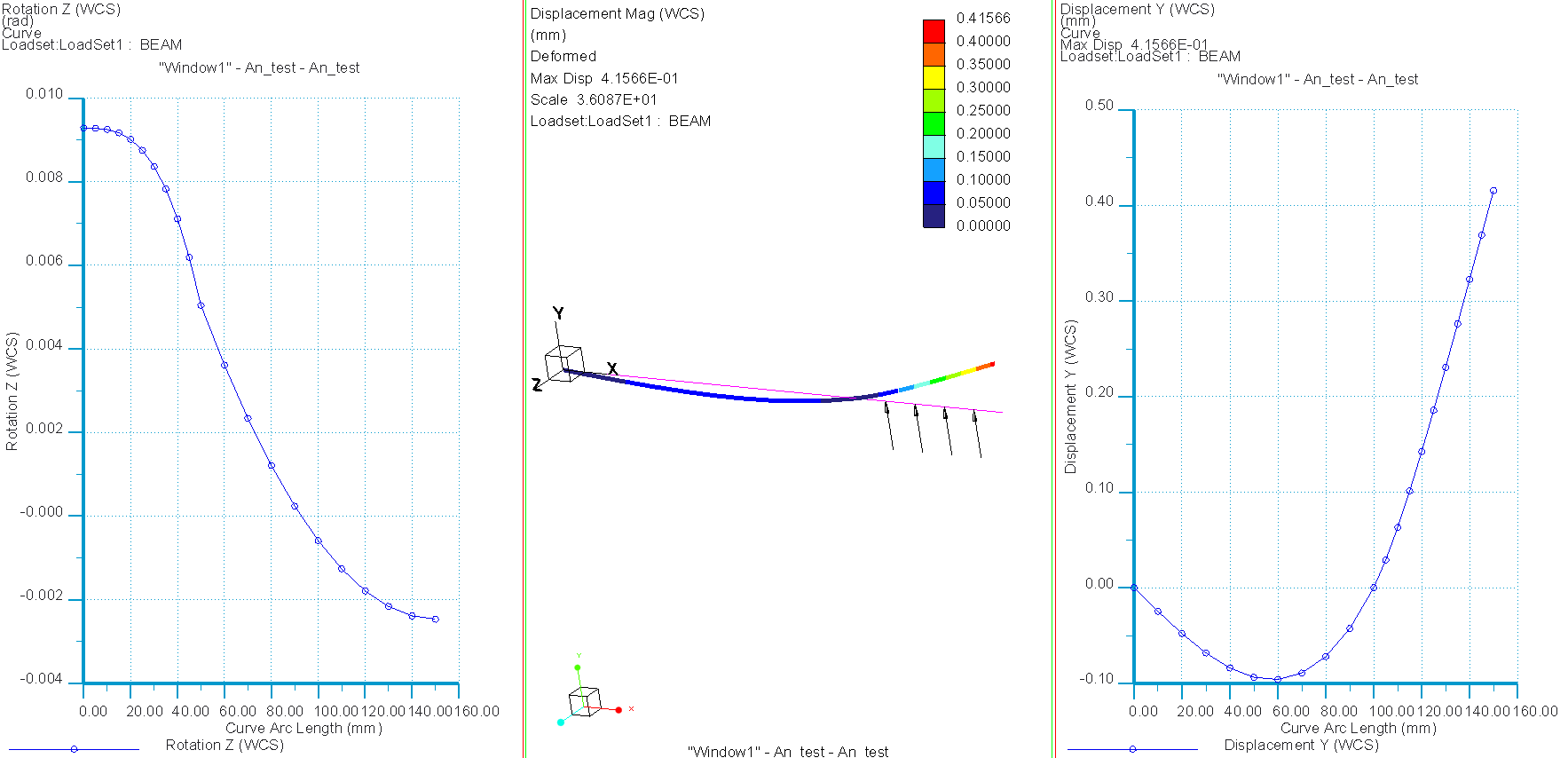
If you increase "plotting grid" to 10, and/or refine mesh and increase max P-level/reduce convergence interval, will you still see rotation discontinuity? This could be an accuracy issue... Also plot rotations, not only displacements, this might give you some additional insight.
To refine mesh, create datum curves for beams as several curves/line segments, then it is possible to create 1 beam element per curve segment. Or create "point-to-point" beams, using several point per "beam" so as to create more elements. Use right mouse button / "query select" to select only a curve segment, and not the entire sketch, to create a single beam element for a single curve segment. See attached model...
Best regards Mats Lindqivst
Dec 04, 2015
03:31 PM
- Mark as New
- Bookmark
- Subscribe
- Mute
- Subscribe to RSS Feed
- Permalink
- Notify Moderator
Dec 04, 2015
03:31 PM
Massimo: A region on a line? No I think you should define a load as a function of coordinates. You can use booleans like If (x>100, 1000,0) which would give a load of 1000 for x>100 and a load of 0 for x<100.
Regards
Erik Haenen
