
Turn on suggestions
Auto-suggest helps you quickly narrow down your search results by suggesting possible matches as you type.
Showing results for
Turn on suggestions
Auto-suggest helps you quickly narrow down your search results by suggesting possible matches as you type.
Showing results for
Community Tip - Stay updated on what is happening on the PTC Community by subscribing to PTC Community Announcements. X
- Community
- Creo+ and Creo Parametric
- 3D Part & Assembly Design
- Re: Setting up accurate isometric views
Options
- Subscribe to RSS Feed
- Mark Topic as New
- Mark Topic as Read
- Float this Topic for Current User
- Bookmark
- Subscribe
- Mute
- Printer Friendly Page
Setting up accurate isometric views
Nov 23, 2012
02:36 PM
- Mark as New
- Bookmark
- Subscribe
- Mute
- Subscribe to RSS Feed
- Permalink
- Notify Moderator
Nov 23, 2012
02:36 PM
Setting up accurate isometric views
It has become apparant that the use of true ISO views by default is not a worthy quest by PTC.
In my world, however, it is very important.
Although a dynamic orientation of 45 and 35.264 is close, it is not a true ISO as you will see by the datum planes not lining up.
So here goes a how-too to easily set up your 1st ISO view -correctly- from which subsequent ISO views can be created.
this process can be done at anytime in any model.
1) If you haven't done so already, open a part or assembly. We will start with a blank part so an ISO view can be added to a fresh template.
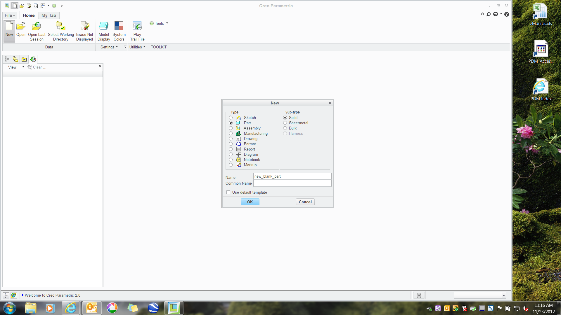
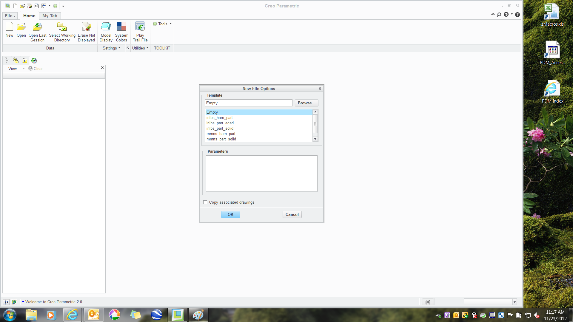
2) In order to have a completely virgin part, an empty template is selected.
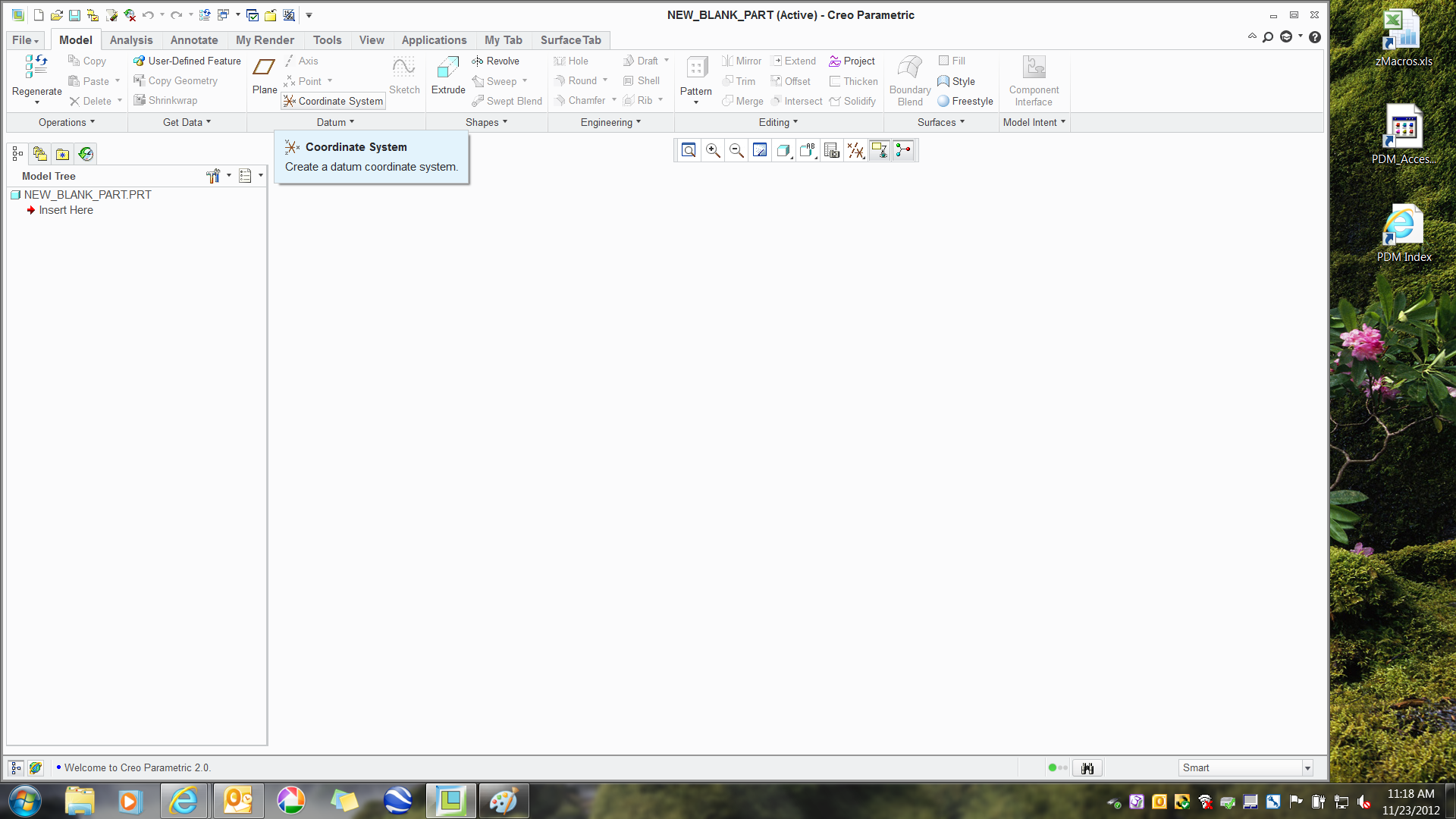
3) Click on Coordinate System. The default coordinate system will be created.
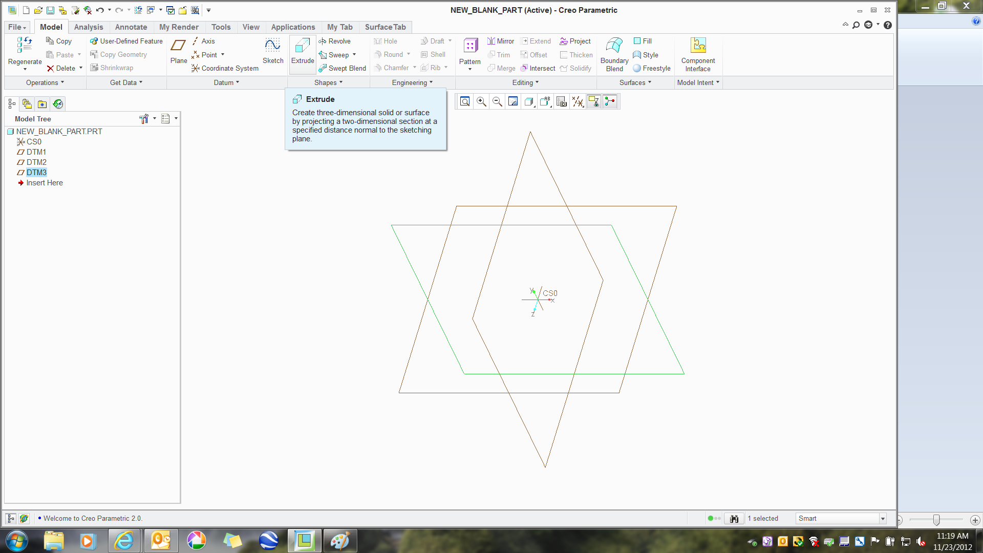
4) Click on Create Datum Plane. The 3 default datum planes will be created.

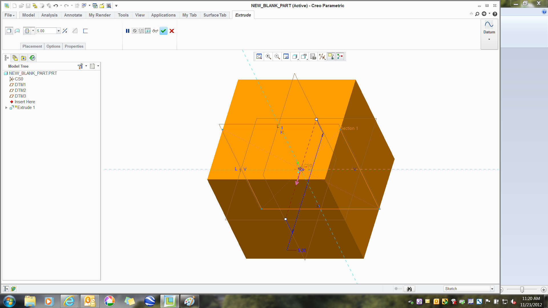
5) We will extrude a cube.
6) Set the cube size common to your general application.
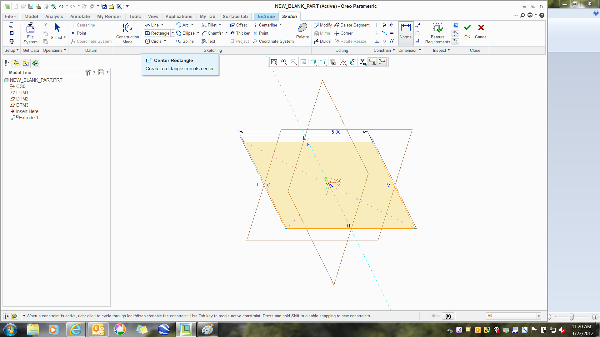
7) Cube is center-offset to the same as the sketch size; in this case, 5 (...this is important!)
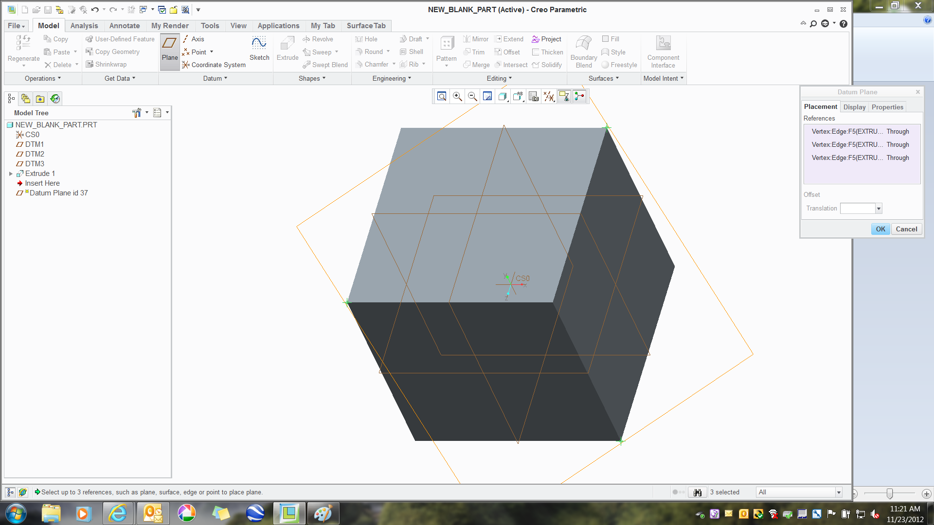
😎 Create a Datum Plane using the 3 points on the cube as shown; upper left, upper right, and lower corner.
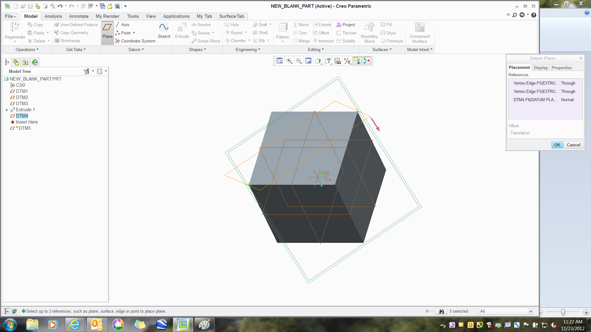
9) Create a perpendicular plane to DTM4 with 2 points used previously and DTM4
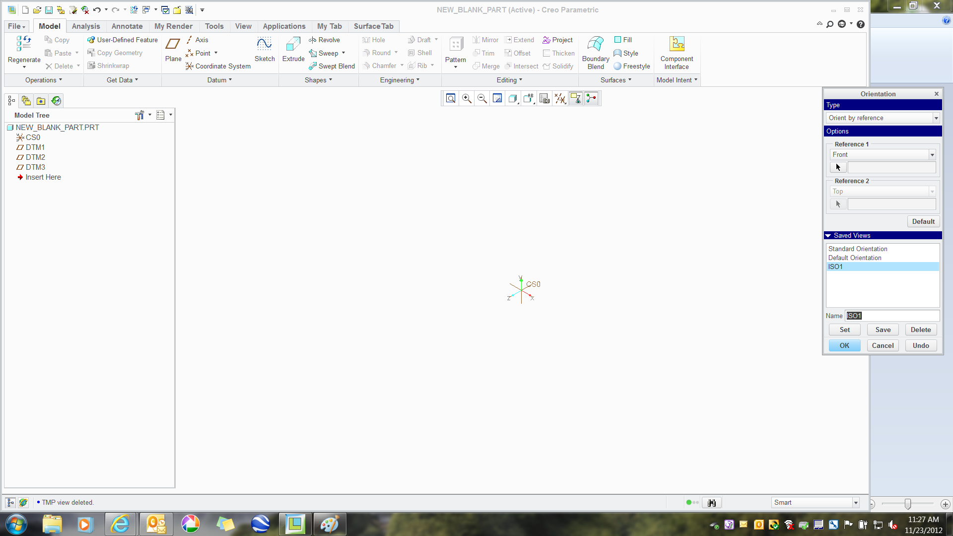
10) Reorient the view as shown in the dialog. DTM4 is the Back and DTM5 is the Bottom (due to their creation order).
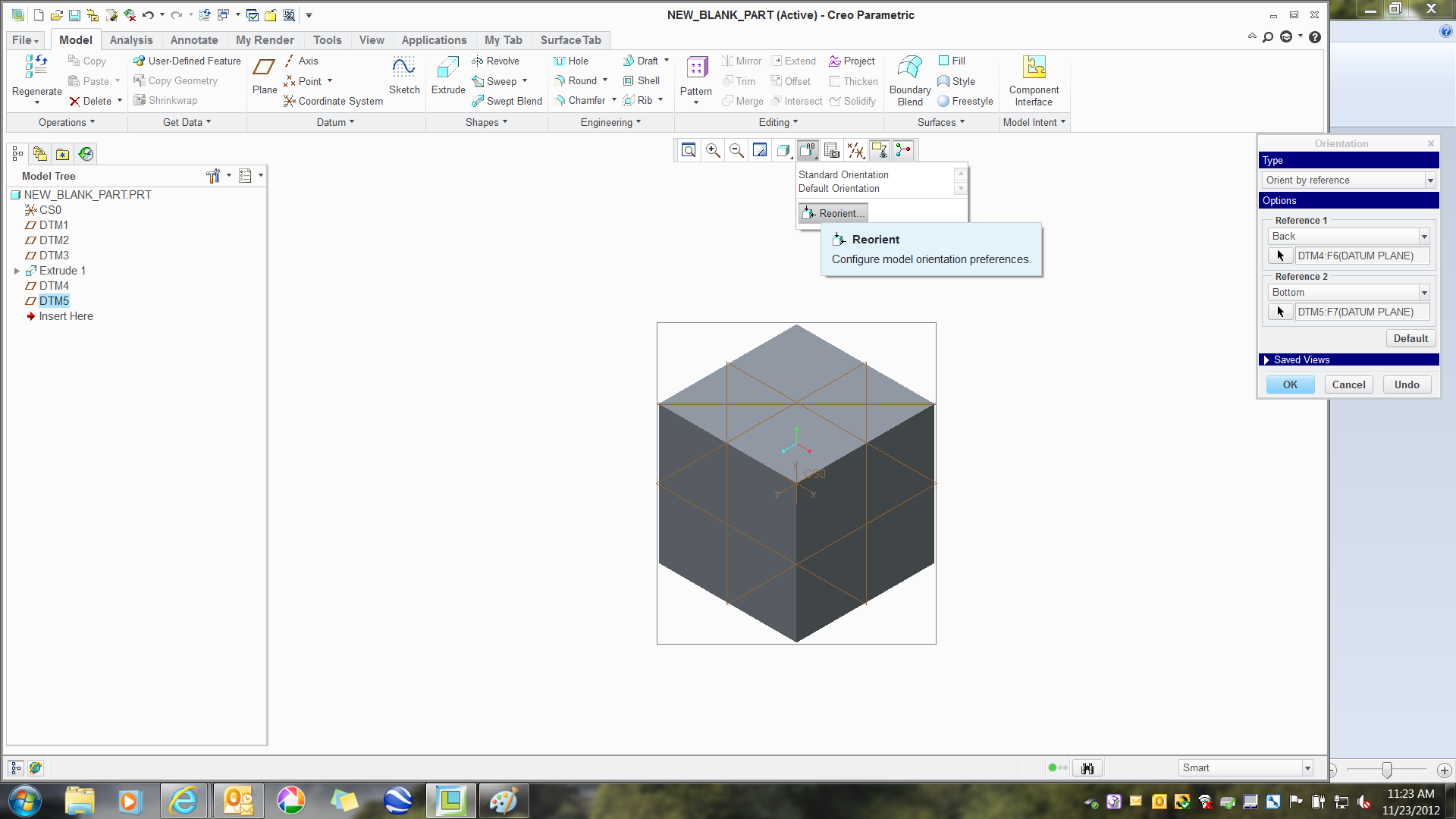
11) Name this view TMP and Save (you will see why in a second).
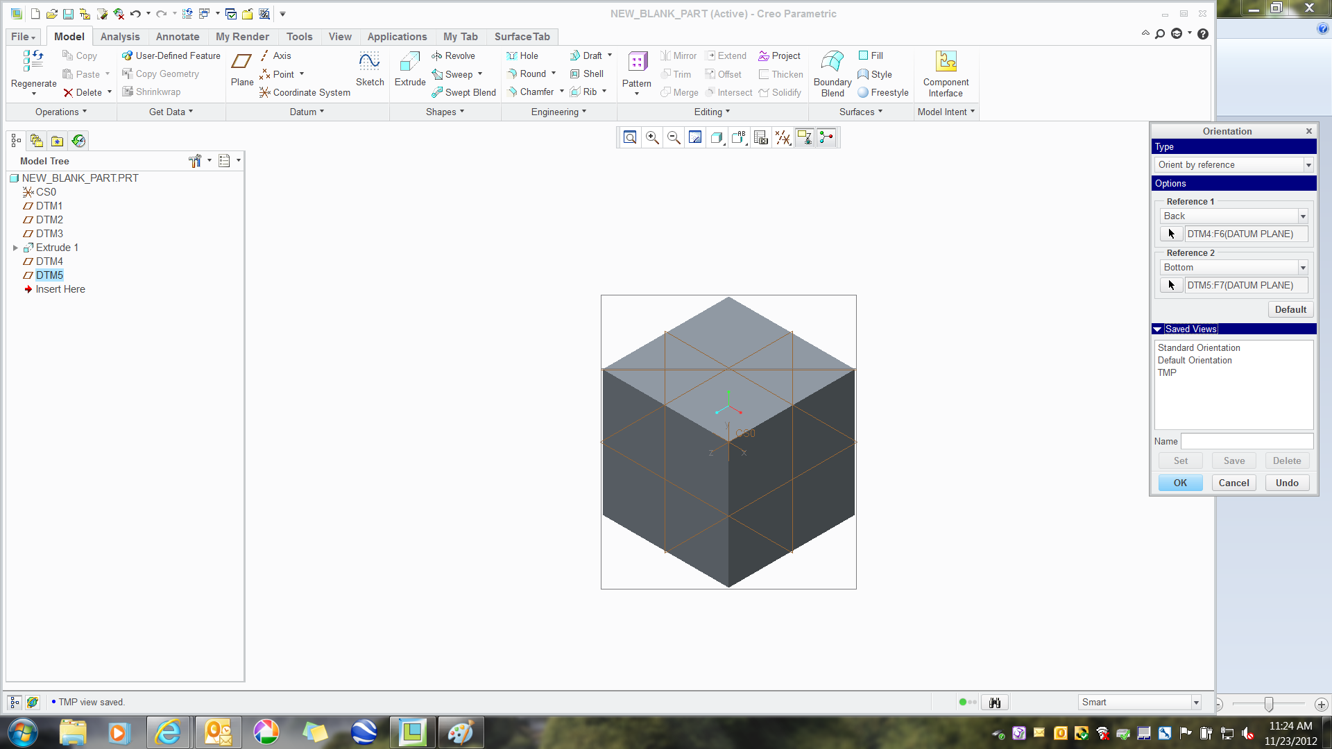
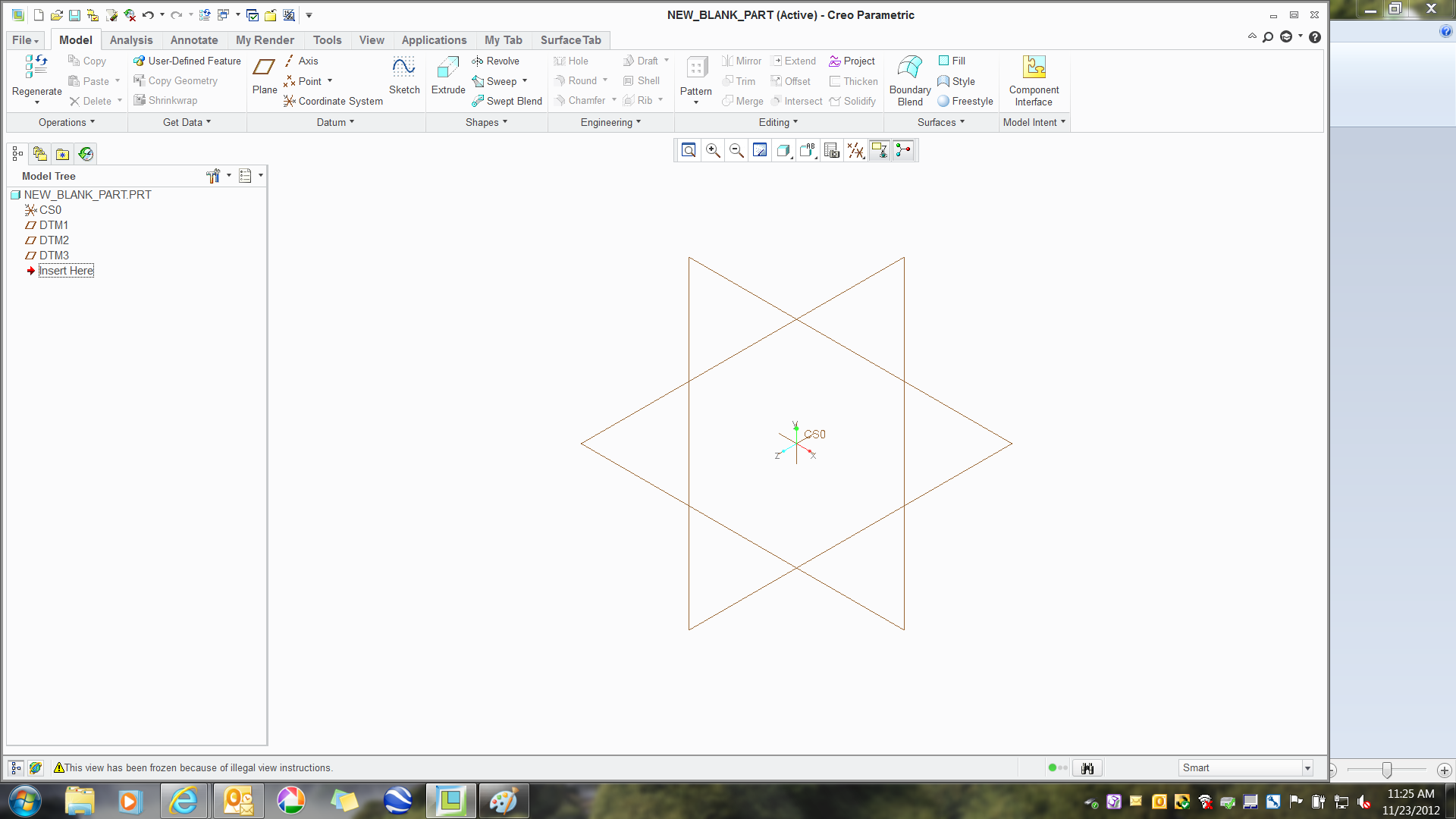
12) Delete the Extrusion, DTM4 and DTM5.
13) Restore the view TMP (reorient/TMP-set). Note the error on the status bar. Now name a new view ISO1 and Save.
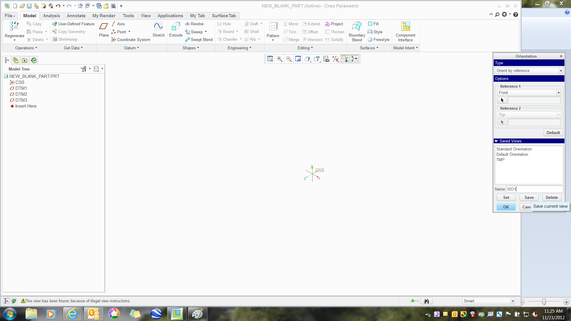
14) Delete view TMP (Hint - View TMP no longer has its references where ISO1 didn't use any, hense the error.)

15) Your datum planes may disappear now since the model no longer has a geometry-defined bounding box. No worries. Restore view ISO1 if needed.
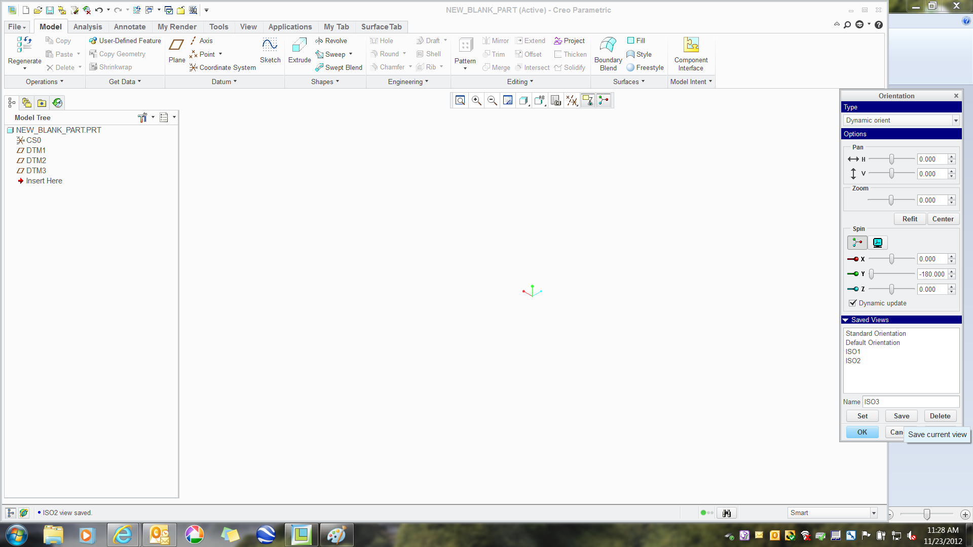
16) Use Dynamic Orient, Model (not view) and move the Y-axis 90 degrees at a time. Save the new view as ISO2.

17) Rinse and repeat... ISO3, ISO4...
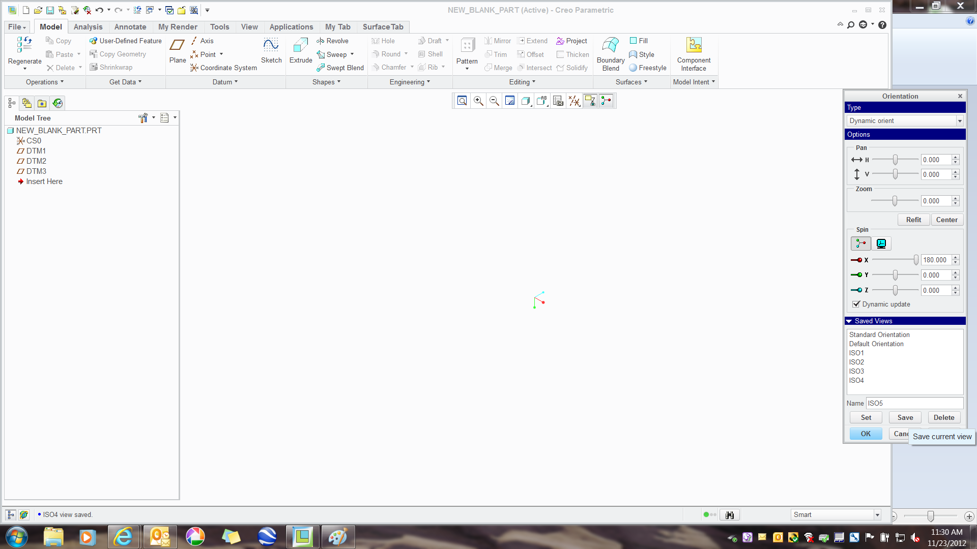
18) To obtain the ever popular "upside down ISO", restore ISO1 and reorient about the X-axis at 180 degrees.
I would have been happy to do this in a video to make the images lighter but I do not have the means at this time. However, I hope you caught the subtleties of this process.
Again, you can do this anywhere in the model creation process. I often have to do this on the fly.
If the view extents are not to your liking after creating a model, you simply restore the view, zoom extent, and save the view again. This will customise the view to your model once geometry has been created.
This thread is inactive and closed by the PTC Community Management Team. If you would like to provide a reply and re-open this thread, please notify the moderator and reference the thread. You may also use "Start a topic" button to ask a new question. Please be sure to include what version of the PTC product you are using so another community member knowledgeable about your version may be able to assist.
Labels:
- Labels:
-
General
- Tags:
- true_isometric_views
2 REPLIES 2
Nov 27, 2012
02:49 AM
- Mark as New
- Bookmark
- Subscribe
- Mute
- Subscribe to RSS Feed
- Permalink
- Notify Moderator
Nov 27, 2012
02:49 AM
High schools insist on having an Isometric view so it is included in the configuration files for Creo Parametric Academic Edition.
Nov 27, 2012
03:28 AM
- Mark as New
- Bookmark
- Subscribe
- Mute
- Subscribe to RSS Feed
- Permalink
- Notify Moderator
Nov 27, 2012
03:28 AM
Curious... is it a view they provide and is it really a true ISO (do the default planes mesh properly?)?
I know you have the option of having the default view be Isometric but when used on a drawing, it is not consistent. If you change the default back to whatever that original view orientation is, all drawing views using ISO will now re-orient.
