
Turn on suggestions
Auto-suggest helps you quickly narrow down your search results by suggesting possible matches as you type.
Showing results for
Turn on suggestions
Auto-suggest helps you quickly narrow down your search results by suggesting possible matches as you type.
Showing results for
Community Tip - If community subscription notifications are filling up your inbox you can set up a daily digest and get all your notifications in a single email. X
- Community
- Creo+ and Creo Parametric
- 3D Part & Assembly Design
- Re: Sheetmetal file corrupted?
Options
- Subscribe to RSS Feed
- Mark Topic as New
- Mark Topic as Read
- Float this Topic for Current User
- Bookmark
- Subscribe
- Mute
- Printer Friendly Page
Sheetmetal file corrupted?
Feb 13, 2013
05:23 AM
- Mark as New
- Bookmark
- Subscribe
- Mute
- Subscribe to RSS Feed
- Permalink
- Notify Moderator
Feb 13, 2013
05:23 AM
Sheetmetal file corrupted?
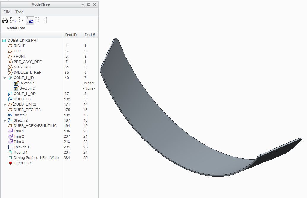
I have a sheet metal part that used to unbend without problems.
A few days later, I have the same file without changes made to it, and it doesn't unbend anymore.
I get the error message " innapropriate edge selected " if I try to unbend it again.
I tried many things, including deleting some of the latest features, and creating the sheet metal part again. Nothing works.
Recreating the whole part from scratch again will be very much work, because it is completely parameter/relation driven.
At the same time as the first part, I created a second part witch has the first part inside it (merge/inheritance) , and has the unbend feature already created. This part still unbends, even when I delete the unbend feature, and add the unbend feature again.
If I try to recreate this file in the exact same way (new file --> merge/inheritance --> create driving surface) it works up until the unbend feature. This will now also fail with the same message (innapropriate edge).
My computer/creo might have crashed between when it used to work and now, I don't remember.
Is there a way to resolve this kind of problems? ( let creo or a tool check for problems inside the file?)
I looked everywhere inside the file, there is no message or hint anywhere that indicates anything wrong.
This thread is inactive and closed by the PTC Community Management Team. If you would like to provide a reply and re-open this thread, please notify the moderator and reference the thread. You may also use "Start a topic" button to ask a new question. Please be sure to include what version of the PTC product you are using so another community member knowledgeable about your version may be able to assist.
Labels:
- Labels:
-
General
6 REPLIES 6
Feb 13, 2013
08:02 AM
- Mark as New
- Bookmark
- Subscribe
- Mute
- Subscribe to RSS Feed
- Permalink
- Notify Moderator
Feb 13, 2013
08:02 AM
UPDATE: After 3 hours searching, trying, getting angry and cursing everything on my desk I found something that looks like a solution, but if I may quote Mr. Spock: it's illogical.
SITUATION: I have a sheet metal part that has some intelligence included. It is a plate that follows the form of the surface it is placed on. The 'mother surface' can be a cylinder, a cone or an eccentric cone. In some cases, the unbending works like a charm, in most cases I cannot place the unbend feature because I cannot select a fixed geometry. Here I get the error "innapropriate edge".
SOLUTION: If I change the parameters to make the "mother surface" very easy, like a cylinder, I can create the unbend feature. I have to do this in a second part, with the merge/inheritance function because the main part must always be in the bent situation. Once created, I can change the parameters to whatever I want, the unbend feature will keep on working without a problem. Sizes and forms that previously failed, are now not a problem anymore.
REMARK: I think Creo has a bug somewhere in the unbend feature. In my opinion, the unbend has to possible in all cases, from the first time, not only with a detour...
INFO: the version I'm currently working with: Creo Parametric 2.0 M030
Feb 13, 2013
11:42 AM
- Mark as New
- Bookmark
- Subscribe
- Mute
- Subscribe to RSS Feed
- Permalink
- Notify Moderator
Feb 13, 2013
11:42 AM
This must be your saddle challenge 
When you created your eccentric cone, was it done in sheetmetal or did you convert it after the fact?
Feb 18, 2013
07:15 AM
- Mark as New
- Bookmark
- Subscribe
- Mute
- Subscribe to RSS Feed
- Permalink
- Notify Moderator
Feb 18, 2013
07:15 AM
Yes it is the saddle challenge... I'll be a saddle-master soon... 
Because I don't know in advance the type of vessel the saddle is on (conical, eccentric cone, cylinder), I created the internal surface of the vessel with a blend. This is in my opinion the only way to create all 3 surfaces controlled with parameters and relations. (there are in reality some more parameters to take into account, like a slope and a shift of the axis for the eccentric cone, that I didn't mention because that will bring us too far).
This surface is offseted to create the outer surface of the vessel (this is also the inner surface of the saddle plate).
This final surface is trimmed to get the final form of the saddle plate. The trim definitions are depending on parameters and on other items of the saddle.
After this, the surface is thickened and converted to sheet metal.
Because of the option for an eccentric cone, it is not possible to create a sheetmetal part from the beginning.
But nevertheless, it is strange that I can alter all parameters and dimensions without any problems, IF the unbend feature is already there. And if I want to unbend the part AFTER I played with the parameters, the unbend is not possible anymore...
Feb 18, 2013
02:40 PM
- Mark as New
- Bookmark
- Subscribe
- Mute
- Subscribe to RSS Feed
- Permalink
- Notify Moderator
Feb 18, 2013
02:40 PM
I had a similar problem in my studies. When I placed a form across a "seam" (a Creo arbitrary seam) the form would no longer flatten. If the form was in a solid region, it worked fine.
Sometimes we will never really understand the inner working of these modules. Sheetmetal in particular is very touchy simply due to the fact that it must take into account edge distortion.
But then again, we pay a lot of money for maintenance, and part of that include expert help for the extensions we pay for. These are productivity tools that need to be understood, and they need to be robust. I see no reason why you cannot demand this error be investigated to an extent where you understand what went wrong.
I learn a lot from files generated by extensions. They show that most of this is done using basic Creo functionality in special ways. Sometimes the amount of data generated is exhausting when the requirement, such as yours, seem so simple on the face of it.
Does EVX specifically support eccentric cones and saddles?
Feb 19, 2013
03:19 AM
- Mark as New
- Bookmark
- Subscribe
- Mute
- Subscribe to RSS Feed
- Permalink
- Notify Moderator
Feb 19, 2013
03:19 AM
At this moment we are not working with EVX yet. The saddles we are currently designing are not in EVX, they are very 'normal' creo-models.
We still need some training to learn how to set up EVX-models. These are in fact normal Creo models, but with some pre-defined conventions in naming of features, layers, ... If you would create a model with EVX, you can open it afterwards in a normal Creo environment without problems.
Normally EVX comes with a pre-defined set of pressure vessel parts like shells, heads, nozzles. This is a great set if you make basic pressure vessels. But... we don't ... 
Our speciality lies in very special and difficult pressure vessels in exotic materials. So what we'll do basically, is to throw away all parts that are in the basic EVX version, and build ourselves a complete new parts database from scratch.
We will use only the bare skeleton of EVX to create our own super-version. In the standard version, eccentric cones are not supported. We will create them ourself. Also vessels made from explosion-cladded materials, heat exchanger, autoclaves, reactors, ... are not in the standard version.
In our company there are 4 CAD drawers that will use EVX to build up the vessels. 1 of the CAD drawers and I will create the EVX models. We hope to have a fully working set within 1 year, but after that we will continue to create new parts as needed.
Feb 19, 2013
11:03 AM
- Mark as New
- Bookmark
- Subscribe
- Mute
- Subscribe to RSS Feed
- Permalink
- Notify Moderator
Feb 19, 2013
11:03 AM
I can understand that.
It is true that all extension modules embed what is required to open in core Creo. You just cannot add additional features or use the extension feature dialogs unless the license is present. At least, this is what I've been told.
Sounds like you have a year long adventure ahead of you. Let me know if you have any additional challenges.
