
Turn on suggestions
Auto-suggest helps you quickly narrow down your search results by suggesting possible matches as you type.
Showing results for
Turn on suggestions
Auto-suggest helps you quickly narrow down your search results by suggesting possible matches as you type.
Showing results for
Community Tip - When posting, your subject should be specific and summarize your question. Here are some additional tips on asking a great question. X
- Community
- Creo+ and Creo Parametric
- 3D Part & Assembly Design
- Re: Thin wall enclosure subjected to external pres...
Options
- Subscribe to RSS Feed
- Mark Topic as New
- Mark Topic as Read
- Float this Topic for Current User
- Bookmark
- Subscribe
- Mute
- Printer Friendly Page
Thin wall enclosure subjected to external pressure
Feb 11, 2013
08:00 PM
- Mark as New
- Bookmark
- Subscribe
- Mute
- Subscribe to RSS Feed
- Permalink
- Notify Moderator
Feb 11, 2013
08:00 PM
Thin wall enclosure subjected to external pressure
Hello,
I simulates a small thin walled cylinder, closed at both ends.
It is subjected to external pressure.
To have no constraints, I am Loading inertial balance.
I run the simulation, I travel and the stress on the entire piece.
I cut the cylinder in two lengthwise through the axis.
I divide my pressure 2.
In the example of manual Wildfire 2.0 belt buckle.
I place restrictions of symmetry of the cutting face.
I run the simulation, I travel and constraints, but not the same values as before, totally different.
In this case, I only deformation of the cylinder on the edge of the cutting cylinder, but not elsewhere.
For this type of simulation should proceed in a specific manner.
Cordially.
Denis
This thread is inactive and closed by the PTC Community Management Team. If you would like to provide a reply and re-open this thread, please notify the moderator and reference the thread. You may also use "Start a topic" button to ask a new question. Please be sure to include what version of the PTC product you are using so another community member knowledgeable about your version may be able to assist.
Labels:
- Labels:
-
General
9 REPLIES 9
Feb 13, 2013
02:30 AM
- Mark as New
- Bookmark
- Subscribe
- Mute
- Subscribe to RSS Feed
- Permalink
- Notify Moderator
Feb 13, 2013
02:30 AM
Hello,
you don't have to divide the pressure by 2.
As it's a pressure, dividing the area by 2 will decrease the load by 2.
I never used the symmetry restriction, so I cannot help you any more.
Feb 14, 2013
07:48 AM
- Mark as New
- Bookmark
- Subscribe
- Mute
- Subscribe to RSS Feed
- Permalink
- Notify Moderator
Feb 14, 2013
07:48 AM
I have an idea, but not sure, if u take the complete cylinder and place constraints at both edges with axial fixed and transverse free movement.
Feb 14, 2013
08:07 AM
- Mark as New
- Bookmark
- Subscribe
- Mute
- Subscribe to RSS Feed
- Permalink
- Notify Moderator
Feb 14, 2013
08:07 AM
I agree with Sylvain that you don't want to change your pressure. With inertia relief, displacement values can be quite different as you will see some rigid motion reflected in the displacement results. Are your stress results similar between the full model and the symmetry model?
Also, as Jayanta mentioned, you can use constraints to mimic the symmetry condition. You can probably come up with a 3-point constraint method that allows you to get rid of inertia relief in the full model. A cylinder closed at both ends with pressure applied should have a net zero load in all directions...the inertia relief solution should only be adding the "SUPORT" points and not any measurable body loads.
Brad Green
Feb 14, 2013
08:48 AM
- Mark as New
- Bookmark
- Subscribe
- Mute
- Subscribe to RSS Feed
- Permalink
- Notify Moderator
Feb 14, 2013
08:48 AM
For a cylindrical tank, I would have used an 2D axisymmetric model.
Just one comment: there isn't any question in Denis' message... 
Denis, si vous êtes francophone, pouvez-vous poser votre question en français ?
Je ne suis pas sûr d'avoir bien saisi vos explications et votre problème.
Feb 14, 2013
01:17 PM
- Mark as New
- Bookmark
- Subscribe
- Mute
- Subscribe to RSS Feed
- Permalink
- Notify Moderator
Feb 14, 2013
01:17 PM
Hello,
Thank you for your answers.
Sylvain, effectivement je suis francophone et malheureusement je ne parle pas anglais.
J'utilise un traducteur automatique pour écrire et lire les messages.
J'ai un cylindre fermé aux extrémités et cet ensemble est enfermé dans une enceinte sous pression.
Ce qui m'intéresse c'est d'avoir une épaisseur au minimum de matière de la paroi.
Quand on simule la pièce entière, on ne voit pas bien les déformations, identiques sur tout le pourtour du tube,
on peut utiliser la fonction Surface de Coupe/Section pour les visualiser.
Maintenant si on simule un demi-cylindre avec la Restriction Symétrie, puisque l'on est coupé par le milieu,
on pourrait n'en prendre que le quart en utilisant la Restriction Cylique, etc.
Mais dans le cas de la coupe par le milieu du tube, je trouve des déformations plus importantes
que sur la pièce entière et les déformations sont localisées sur les flancs du tube.
Bien sûr, j'utilise toujours la même pression.
Pour la division de la pression par 2, j'avais regardé l'exemple du manuel de la WF2 sur l'étude d'une boucle
de ceinturon, où il étudiait la moitié de la forme, cette dernière étant symétrique et divisée en deux,
la force d'ouverture était, elle aussi divisée par 2.
Ci-joint une vue de la pièce simplifiée.
Cordialement.
Denis
Feb 14, 2013
01:19 PM
- Mark as New
- Bookmark
- Subscribe
- Mute
- Subscribe to RSS Feed
- Permalink
- Notify Moderator
Feb 14, 2013
01:19 PM
Désolé j'ai appuyé trop vite.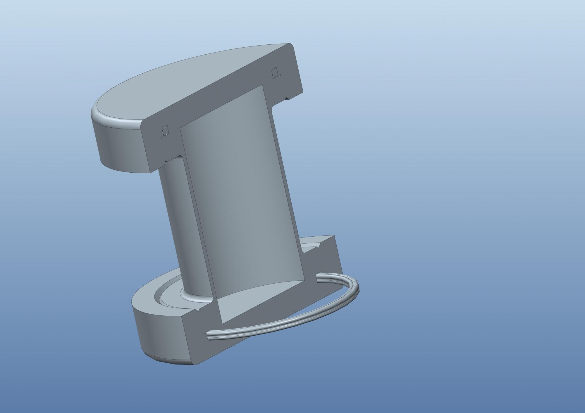
Feb 15, 2013
02:34 AM
- Mark as New
- Bookmark
- Subscribe
- Mute
- Subscribe to RSS Feed
- Permalink
- Notify Moderator
Feb 15, 2013
02:34 AM
You can simply insert a cutting/capping surface as you mentioned. The deformation should be identical all aroud the cylinder as it is an axisymmetric part.
Denis, pourquoi n'avez-vous pas simplement inséré une surface de coupe comme vous l'avez mentionné?
Cela vous permettra de visualiser parfaitement la déformation du tube. (la pièce étant axisymétrique, la déformation devrait être la même sur tout le pourtour)
I guess that, in the belt buckle example, the load applied was a force and not a pressure.
That's why the load has to be divided by 2 when adding a symmetry restriction, which is not needed with a pressure load.
J'imagine que dans l'exemple de la boucle de ceinture la charge appliquée était une force et non une pression.
C'est pourquoi il fallait la diviser par 2 lors d'une restriction de symétrie, ce qui n'est pas le cas avec une pression.
Could you add a picture of the constrained/loaded parts and one of the deformed parts ? (both cases: half part/whole part)
It seems obvious that the deformations are localized at the cylinder wall as it is much thinner than the rest of the model.
Pouvez-vous nous montrer une image de votre pièce où les contraintes et charges seraient visibles et une image des pièces déformées ? (une image pour le modèle entier et une pour le modèle coupé en deux)
Il me parait logique que les déformations soient localisées sur les parois du cylindre, le reste de la pièce étant relativement massif.
For english-speaking users, here is a translation of Denis' issue (Denis doesn't speak english and has used an auto-translator):
A thin cylinder, closed at both ends, is enclosed in a tank which is under pressure.
The goal of the study is to have a wall as thin as possible.
After studying the whole model, the resulting deformations are not easily visualized by Denis.
He knows he can add a cutting/capping surface but he wanted to try to cut the part and add a symmetry restriction.
He divided the pressure by 2 because of the belt buckle example in the WF2 manual.
Deformations of the half part are larger than those of the whole part and are localized at the cylinder wall.
Feb 15, 2013
03:46 AM
- Mark as New
- Bookmark
- Subscribe
- Mute
- Subscribe to RSS Feed
- Permalink
- Notify Moderator
Feb 15, 2013
03:46 AM
I believe I have spotted the problem...
When you use Inertia Relief, I believe that all other constraints are disabled - including any symmetry constraints. I think we found this fairly recently, trying to run a cyclic symmetry with inertia relief...
In short, you can't use Inertia Relief and symmetry constraints at the same time.
If the loads are balanced, I have often had good results applying a constraint to a point or edge, away from any of the high-stress areas, so that Mechanica doesn't see the model as unconstrained. If there are any residual loads, it's easy to see if there are stresses near this constraint and either ignore them or correct the loads.
Desolée, je comprends un peu votre Francais, mais je ne peut pas l'ecrire assez bien...
Feb 16, 2013
10:54 AM
- Mark as New
- Bookmark
- Subscribe
- Mute
- Subscribe to RSS Feed
- Permalink
- Notify Moderator
Feb 16, 2013
10:54 AM
Hello,
Thank you for your help and answers.
Sylvain, yes indeed pressure must not divide by 2 as in the case of force.
Jonathan
Thank you for your experience, you can not use at the same time restricting the symmetric and inertial loading.
I remade my simulation and now the result is correct.
In my cup, this time I'm deformation all the way around the cylinder.
Cordially.
Denis
