
Turn on suggestions
Auto-suggest helps you quickly narrow down your search results by suggesting possible matches as you type.
Showing results for
Turn on suggestions
Auto-suggest helps you quickly narrow down your search results by suggesting possible matches as you type.
Showing results for
Community Tip - New to the community? Learn how to post a question and get help from PTC and industry experts! X
- Community
- Creo+ and Creo Parametric
- 3D Part & Assembly Design
- UDF for holes, with reference pattern
Options
- Subscribe to RSS Feed
- Mark Topic as New
- Mark Topic as Read
- Float this Topic for Current User
- Bookmark
- Subscribe
- Mute
- Printer Friendly Page
UDF for holes, with reference pattern
Mar 07, 2020
12:38 PM
- Mark as New
- Bookmark
- Subscribe
- Mute
- Subscribe to RSS Feed
- Permalink
- Notify Moderator
Mar 07, 2020
12:38 PM
UDF for holes, with reference pattern
I want to make an UDF, but i’m not finding a way to do it.
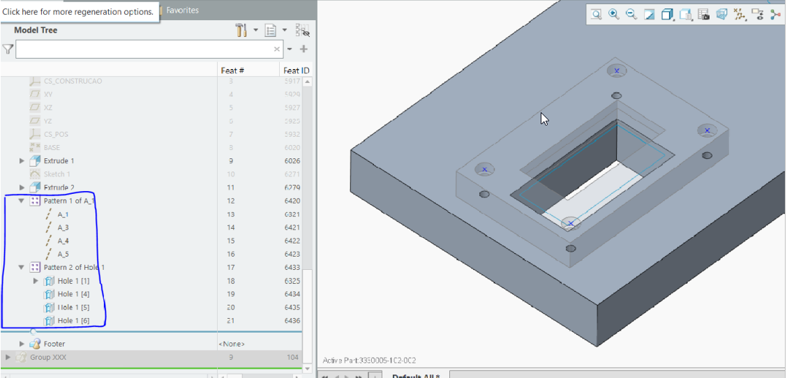
I have two parts, one in the top, other in the bottom. In the top the part has a hole feature created, and propagated with pattern. In the bottom part, i have created an axis system centered in one of the holes, patterned (with reference), and then created a hole centered in the previous axis system and patterned as well with reference.
Now I want to make an UDF, to generate all the holes in the bottom part. But as this holes were created with reference with top part, I’m unable to create it.
When I’m in the step to select the features, that belong to UDF, it appears the following message:
“Including pattern (feat id 6420) by reference must include its reference (feat id 6061, model 3330005-102-001) or entire reference model.”
My question is, how can i select this features, and at the same time, includ its reference?
At the end in the UDF, I only want to select the cylindrical surface of one hole of the top part, select the top surface of the top plane, and the result, os 4 holes generated.
Any tips?
Labels:
- Labels:
-
General
9 REPLIES 9
Mar 07, 2020
02:13 PM
- Mark as New
- Bookmark
- Subscribe
- Mute
- Subscribe to RSS Feed
- Permalink
- Notify Moderator
Mar 07, 2020
02:13 PM
Your approach has issues with parent child relationships as you have discovered. Is a UDF the only acceptable method for you to manage this?
I would suggest the use of reference patterns and an external copy geometry feature. Pattern the hole centers of the top part using an array of datum points. Use this pattern to place the holes in both the top and bottom parts.
You can use a copy geometry of the pattern leader (only copy the pattern leader and nothing else in the copy geom feature) from the top part to the bottom part and then you can pattern by reference the hole in the bottom and they will stay aligned to the top. You would then add the hole to the bottom and pattern by reference.
========================================
Involute Development, LLC
Consulting Engineers
Specialists in Creo Parametric
Involute Development, LLC
Consulting Engineers
Specialists in Creo Parametric
Mar 07, 2020
03:13 PM
- Mark as New
- Bookmark
- Subscribe
- Mute
- Subscribe to RSS Feed
- Permalink
- Notify Moderator
Mar 07, 2020
03:13 PM
I would like to create the udf withe the reference pattern inside, because this will be used several times per hour. So if this udf can have inside the pattern, I will be a lot more productive, I won't have the need to make the pattern manually.
Mar 07, 2020
04:58 PM
- Mark as New
- Bookmark
- Subscribe
- Mute
- Subscribe to RSS Feed
- Permalink
- Notify Moderator
Mar 07, 2020
04:58 PM
I would benefit from understanding your design intent completely to narrow done some options. Do you need a stand alone or subordinate UDF? Does the hole spacing change each time you place it? What method would you use to copy the location of the pattern leader from the top plate to the bottom plate? Would it be done in assembly mode or part mode?
You can not include a copy geom in UDF creation so that is out. You have to establish a method of mapping the leader of the pattern in the top to the bottom plate in a manner that can be used in a UDF creation. The only thing that comes to mind for this is to use relations to control the position in the bottom plate based on values set in the top plate.
I would use a layout to do this if using relations. You would set the values in the layout and then use the layout to drive the position and spacing of both hole sets in top and bottom parts.
Have you considered creating a reference part with the pattern and then use copy paste to place the hole pattern in a given part. I use paste special to do similar operations quickly without UDF creation.
========================================
Involute Development, LLC
Consulting Engineers
Specialists in Creo Parametric
Involute Development, LLC
Consulting Engineers
Specialists in Creo Parametric
Mar 07, 2020
07:23 PM
- Mark as New
- Bookmark
- Subscribe
- Mute
- Subscribe to RSS Feed
- Permalink
- Notify Moderator
Mar 07, 2020
07:23 PM
Can you show me an example of this?
"Have you considered creating a reference part with the pattern and then use copy paste to place the hole pattern in a given part. I use paste special to do similar operations quickly without UDF creation"
I think I haven't understand properly your idea. I think that I'm unable also to copy the pattern made with reference!
Mar 07, 2020
11:29 PM
- Mark as New
- Bookmark
- Subscribe
- Mute
- Subscribe to RSS Feed
- Permalink
- Notify Moderator
Mar 07, 2020
11:29 PM
Cut and paste is supported for features for inter and intra model use. Copy of patterned features is supported.
ctrl+c ; copy
ctrl+v ; paste
shift+ctrl+v; for paste special (this hot key is only available in Creo 4+)
You can select one or more features for these operations when using this functionality. Paste special will enable the selection of new references.
========================================
Involute Development, LLC
Consulting Engineers
Specialists in Creo Parametric
Involute Development, LLC
Consulting Engineers
Specialists in Creo Parametric
Mar 08, 2020
08:34 AM
- Mark as New
- Bookmark
- Subscribe
- Mute
- Subscribe to RSS Feed
- Permalink
- Notify Moderator
Mar 08, 2020
08:34 AM
Copy of patterned features with reference is possible? Something is missing me.
Mar 08, 2020
01:41 PM
- Mark as New
- Bookmark
- Subscribe
- Mute
- Subscribe to RSS Feed
- Permalink
- Notify Moderator
Mar 08, 2020
01:41 PM
Yes you can cut and paste reference patterned features. I just did it on a test part to confirm it is working as previously (Creo 4 M110). I copied 8 features consisting of two patterns, the first is 4 dtm points and the second is 4 holes ref patterned to the points. I copied them from one model to another without issue.
========================================
Involute Development, LLC
Consulting Engineers
Specialists in Creo Parametric
Involute Development, LLC
Consulting Engineers
Specialists in Creo Parametric
Mar 08, 2020
05:44 PM
- Mark as New
- Bookmark
- Subscribe
- Mute
- Subscribe to RSS Feed
- Permalink
- Notify Moderator
Mar 08, 2020
05:44 PM
But what I can gain with this workflow. Can you show me an example, I think I havn't see the complete picture. But anyway, isn't there any way to make this UDF?
Mar 10, 2020
11:51 AM
- Mark as New
- Bookmark
- Subscribe
- Mute
- Subscribe to RSS Feed
- Permalink
- Notify Moderator
Mar 10, 2020
11:51 AM
I was able to place 8 features by selecting one set of references one time. Much faster than creating the 8 features for this example. The trick as with most Creo design intent is to be clever about parent child relationships. Copy paste is not always the best solution but I use it quite often.
UDFs are a powerful tool but you need to understand fully how they will be deployed and used in the modeling process and write a specification for them before creating them, this spec should include the refs and how they will be placed in models. You should retain the spec documentation for future reference. Use the spec to create and test the UDF during creation, for complex UDFs I would test intermediate definitions to insure the references capture intent.
To define common interface locations between parts I would use one of the top down tools such as a skeleton to define shared locations and interfaces. If two or more parts are driven by the skeleton you will save a lot of time making edits. It requires more work up front but will pay back more than 1X. Your example on stacked plates with holes and cuts needing alignment would lend it self to this approach.
========================================
Involute Development, LLC
Consulting Engineers
Specialists in Creo Parametric
Involute Development, LLC
Consulting Engineers
Specialists in Creo Parametric
