
Turn on suggestions
Auto-suggest helps you quickly narrow down your search results by suggesting possible matches as you type.
Showing results for
Turn on suggestions
Auto-suggest helps you quickly narrow down your search results by suggesting possible matches as you type.
Showing results for
Community Tip - Stay updated on what is happening on the PTC Community by subscribing to PTC Community Announcements. X
- Community
- Creo+ and Creo Parametric
- 3D Part & Assembly Design
- WF5: Using Curve pattern
Options
- Subscribe to RSS Feed
- Mark Topic as New
- Mark Topic as Read
- Float this Topic for Current User
- Bookmark
- Subscribe
- Mute
- Printer Friendly Page
WF5: Using Curve pattern
Jan 28, 2014
11:24 AM
- Mark as New
- Bookmark
- Subscribe
- Mute
- Subscribe to RSS Feed
- Permalink
- Notify Moderator
Jan 28, 2014
11:24 AM
WF5: Using Curve pattern
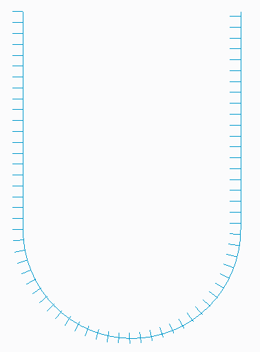
Try this - make a U-shaped datum curve. Then sketch a datum curve spine from the curve in the plane of the U-curve. Then pattern using the Curve option. The shape one should get is a U-shape with a bunch of lttle spines sticking out of the same side, like a beard, if the spine started towards the outside.
What I get in WF5 is spines that float away from the U in the radius portion of the curve and then reattach on the wrong side.
Apparently there is a flawed assumption made by the Curve pattern generator that the geometry is equally biased on the curve.
To 'fix' this I tried to add equal disposition about the curve. So I create the spine like I want, but had a tiny line segment on the other side that extends just as far away. Hopefully the little segment is not noticeable.
I then replaced the tiny segment with a geometry point (not the default sketch point, but the other one). This also worked as long as it was the same distance away from the curve as the furthest extent of the line.
I tried a construction circle, but apparently the flaw is in the geometry duplication stage.
This thread is inactive and closed by the PTC Community Management Team. If you would like to provide a reply and re-open this thread, please notify the moderator and reference the thread. You may also use "Start a topic" button to ask a new question. Please be sure to include what version of the PTC product you are using so another community member knowledgeable about your version may be able to assist.
Solved! Go to Solution.
Labels:
- Labels:
-
General
1 ACCEPTED SOLUTION
Accepted Solutions
Jan 28, 2014
12:49 PM
- Mark as New
- Bookmark
- Subscribe
- Mute
- Subscribe to RSS Feed
- Permalink
- Notify Moderator
Jan 28, 2014
12:49 PM
16 REPLIES 16
Jan 28, 2014
12:49 PM
- Mark as New
- Bookmark
- Subscribe
- Mute
- Subscribe to RSS Feed
- Permalink
- Notify Moderator
Jan 28, 2014
12:49 PM
A picture is worth a thousand words. Same issue in Creo 2.0 M080.
Jan 28, 2014
01:01 PM
- Mark as New
- Bookmark
- Subscribe
- Mute
- Subscribe to RSS Feed
- Permalink
- Notify Moderator
Jan 28, 2014
01:01 PM
Tom, I marked it as correct so you get the points - I am presently bereft of a way to capture and post pictures.
I also found that if I want to project the curves onto a surface, I can't use sketched project and create a datum point. I have to create the pattern of a regular curve, then create a project using the geometry, and then pattern that Reference to the first curve pattern.
Perhaps there could be a YouTube unscripted channel for code reviews where we could see how it was decided that Curve pattern and projected sketches would work the way they do. Sort of like C-Span or sausage factories.
Jan 28, 2014
01:13 PM
- Mark as New
- Bookmark
- Subscribe
- Mute
- Subscribe to RSS Feed
- Permalink
- Notify Moderator
Jan 28, 2014
01:13 PM

use the alternate origin option, and select the start point manually.
i have done this in Pro|Engineer Wildfire 5.0 M010
Jan 28, 2014
01:45 PM
- Mark as New
- Bookmark
- Subscribe
- Mute
- Subscribe to RSS Feed
- Permalink
- Notify Moderator
Jan 28, 2014
01:45 PM
Interesting, thanks!
Jan 28, 2014
01:55 PM
- Mark as New
- Bookmark
- Subscribe
- Mute
- Subscribe to RSS Feed
- Permalink
- Notify Moderator
Jan 28, 2014
01:55 PM
Interesting - so it Alternate Origin can be an option, but it can be a required choice as well.
It must be that the geometry copier is looking at the average extents of the geometry and creating a vector from the first point on the curve to the center of the extents? Have to poke at it more.
Fun and more fun.
Still, pick somewhere else on the model for the Alternate Origin and you'll see odd results.
I'm not sure how it changed your result - the only places I can pick for alternate origin are geometry that exists before the pattern. Other locations sends geometry in other, interesting, but not desireable directions.
Is there other geometry besides the original U-curve and the spine curve in your example?
Jan 28, 2014
04:04 PM
- Mark as New
- Bookmark
- Subscribe
- Mute
- Subscribe to RSS Feed
- Permalink
- Notify Moderator
Jan 28, 2014
04:04 PM
Yes, this is a very common issue.
Rohit's suggestion is wise to use all the time because you wouldn't know it if it was off just a little and things fail.
As far as i'm concerned, this is a serious pattern bug that should be fixed. Having origins follow a seemingly illogical start is simply poor coding.
I'd like to see one of PTC's gurus here on the forum weigh in on this.
Jan 28, 2014
04:14 PM
- Mark as New
- Bookmark
- Subscribe
- Mute
- Subscribe to RSS Feed
- Permalink
- Notify Moderator
Jan 28, 2014
04:14 PM
One problem I do run into all the time with choosing the pattern origin:
It seems that there is usually a pattern node on top of the vertex or point you want to select and there is -no way-, not even with the filter, to select the point you need. The only Pro|Workaround I found for this is to place a CSYS at that location. This is another coding oversight that I am going to have to report one of these days.
Jan 28, 2014
05:16 PM
- Mark as New
- Bookmark
- Subscribe
- Mute
- Subscribe to RSS Feed
- Permalink
- Notify Moderator
Jan 28, 2014
05:16 PM
I hadn't tried it but was thinking the same thing, that using CS's would work as a pattern referenced from points. If you're patterning little datum curves along another curve, maybe making a "geometry" CS within that curve would work as well, since when you place it you need to orient it.
Jan 28, 2014
05:31 PM
- Mark as New
- Bookmark
- Subscribe
- Mute
- Subscribe to RSS Feed
- Permalink
- Notify Moderator
Jan 28, 2014
05:31 PM
Good idea. I really need to report this. Serious oversight on the developer's part.
Jan 28, 2014
06:31 PM
- Mark as New
- Bookmark
- Subscribe
- Mute
- Subscribe to RSS Feed
- Permalink
- Notify Moderator
Jan 28, 2014
06:31 PM
Ok, so, for the first time I played with this. Kind of maddening. I found that if you do not use EXACTLY the endpoint of the trajectory curve as your "alternate origin" that you end up with lines that are not exactly coincident with the trajectory curve. And, you're stuck with the very first instance, though you can turn off any other. It's neat finally being able to do this, but it's got it's quirks for sure.
AND......what would it do on a helical or other 3D curve? Is it smart enough to know, on curvature, what side to be normal to? Towards the center or away from the center? Hmmmm.....
Jan 28, 2014
06:43 PM
- Mark as New
- Bookmark
- Subscribe
- Mute
- Subscribe to RSS Feed
- Permalink
- Notify Moderator
Jan 28, 2014
06:43 PM
Ok, you can't use a 3D curve, only planar.....
Jan 28, 2014
06:53 PM
- Mark as New
- Bookmark
- Subscribe
- Mute
- Subscribe to RSS Feed
- Permalink
- Notify Moderator
Jan 28, 2014
06:53 PM
For fun.....
Of note, when you project things, there is error, I found some mismatches of 0.0000000036. Sounds like nothing, but it could cause a boundary blend or other feature to fail.
Jan 28, 2014
04:10 PM
- Mark as New
- Bookmark
- Subscribe
- Mute
- Subscribe to RSS Feed
- Permalink
- Notify Moderator
Jan 28, 2014
04:10 PM
I did glean an interesting way to pattern points along a 3D curve from another post. Once created, it is a reference pattern for the follow-on pattern.
The idea is to create a point along the 3D curve. Say at .01 ratio along the curve. Use this value as the driving dimension of the pattern. You -can- set the value at zero, but it may fail. You can change it to zero after the fact and it seems to work after that.
I was racking my brain to get this to work before. There are many uses for this tip.
Jan 28, 2014
07:08 PM
- Mark as New
- Bookmark
- Subscribe
- Mute
- Subscribe to RSS Feed
- Permalink
- Notify Moderator
Jan 28, 2014
07:08 PM
long back I had reported this to the CS, this alternate origin suggestion was given to me by the CS only. but I had reported this for "point pattern" and not the curve pattern, I guess the CS was not interested in reporting this to the R&D.
Jan 28, 2014
07:58 PM
- Mark as New
- Bookmark
- Subscribe
- Mute
- Subscribe to RSS Feed
- Permalink
- Notify Moderator
Jan 28, 2014
07:58 PM
True, you have to be prepared to escalate the support case.
I think the logic has something to do with the star point being in the -centroid- (?) of the feature -if- there is no apparant reference that is the same. Obviously, there must be a "like placement or it wouldn't know how to place the3 instances.
I would still like to have PTC comment here. Next time I get into a design dilemma over this and the origin selection, I will report them both in a single case.
Feb 06, 2014
01:49 PM
- Mark as New
- Bookmark
- Subscribe
- Mute
- Subscribe to RSS Feed
- Permalink
- Notify Moderator
Feb 06, 2014
01:49 PM
Ok, so, I was sort of wrong. You cannot select a 3D curve to pattern along. BUT, you can pattern along a 2D curve and use the option "Follow surface shape" and "As projected" to get this:
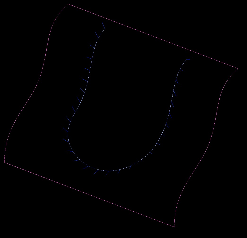
Note: On the "spike" curves, I have a 45deg angle, that's why the spikes are not normal to the curve.
