
Turn on suggestions
Auto-suggest helps you quickly narrow down your search results by suggesting possible matches as you type.
Showing results for
Turn on suggestions
Auto-suggest helps you quickly narrow down your search results by suggesting possible matches as you type.
Showing results for
Community Tip - Learn all about the Community Ranking System, a fun gamification element of the PTC Community. X
- Community
- Creo+ and Creo Parametric
- 3D Part & Assembly Design
- grille pattern with round enclosure
Options
- Subscribe to RSS Feed
- Mark Topic as New
- Mark Topic as Read
- Float this Topic for Current User
- Bookmark
- Subscribe
- Mute
- Printer Friendly Page
grille pattern with round enclosure
Jan 17, 2017
04:39 AM
- Mark as New
- Bookmark
- Subscribe
- Mute
- Subscribe to RSS Feed
- Permalink
- Notify Moderator
Jan 17, 2017
04:39 AM
grille pattern with round enclosure
Hello,
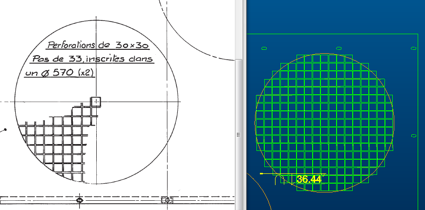
I'm trying to model a grille as shown on the left side of the added picture, but Creo 2.0 gives me the one on the right side.
Any ideas on how to make this happen?
This is a sheet metal part, because the plate is curved. If it were just a solid a would add an extra extrude to fill the excess, but that doesn't work in sheet metal.
Thanks,
Robbie.
Labels:
- Labels:
-
General
4 REPLIES 4
Jan 17, 2017
06:45 AM
- Mark as New
- Bookmark
- Subscribe
- Mute
- Subscribe to RSS Feed
- Permalink
- Notify Moderator
Jan 17, 2017
06:45 AM
I don't know what sequence of operations you attempted on this, but I was able to make a quick version as a flat plate. The steps I took were:
(1) Build a flat sheet, no other features.
(2) Cut out a square pattern to make the grid.
(3) Add an extrude that fills all the square holes and portions of square holes that are outside the circle.
(4) Convert to sheet metal.
Admittedly, I do not use sheetmetal very much, but it seems to be working. By the way, I'm on Creo 2.0.
Jan 17, 2017
10:39 AM
- Mark as New
- Bookmark
- Subscribe
- Mute
- Subscribe to RSS Feed
- Permalink
- Notify Moderator
Jan 17, 2017
10:39 AM
True, that would work and I have considered it, but I don't like converting solids into sheetmetals, unless for simple parts with just a few straight angles.
This plate however is one giant curve, there is no bending, just an arc. Getting the correct curve into the model starting from a flat sheet doesn't seem ideal to me, so I started with a sheetmetal extrude to get the curve right from the start. I know how to put bends on a flat sheet - again, I don't like this method, but it's doable - but a curve I have never tried.
Jan 17, 2017
12:55 PM
- Mark as New
- Bookmark
- Subscribe
- Mute
- Subscribe to RSS Feed
- Permalink
- Notify Moderator
Jan 17, 2017
12:55 PM
If you start it as a sheetmetal extrude, does it then let you unbend it? Could you then do the cuts in the flat, then re-bend? Again, I don't use sheetmetal much. The parts we work on that have sheet metal are either trivially simple, or have complex curvature that sheetmetal can't handle.
Jan 17, 2017
06:55 PM
- Mark as New
- Bookmark
- Subscribe
- Mute
- Subscribe to RSS Feed
- Permalink
- Notify Moderator
Jan 17, 2017
06:55 PM
You can make cuts to a sheet-metal part using thickened surface elements:
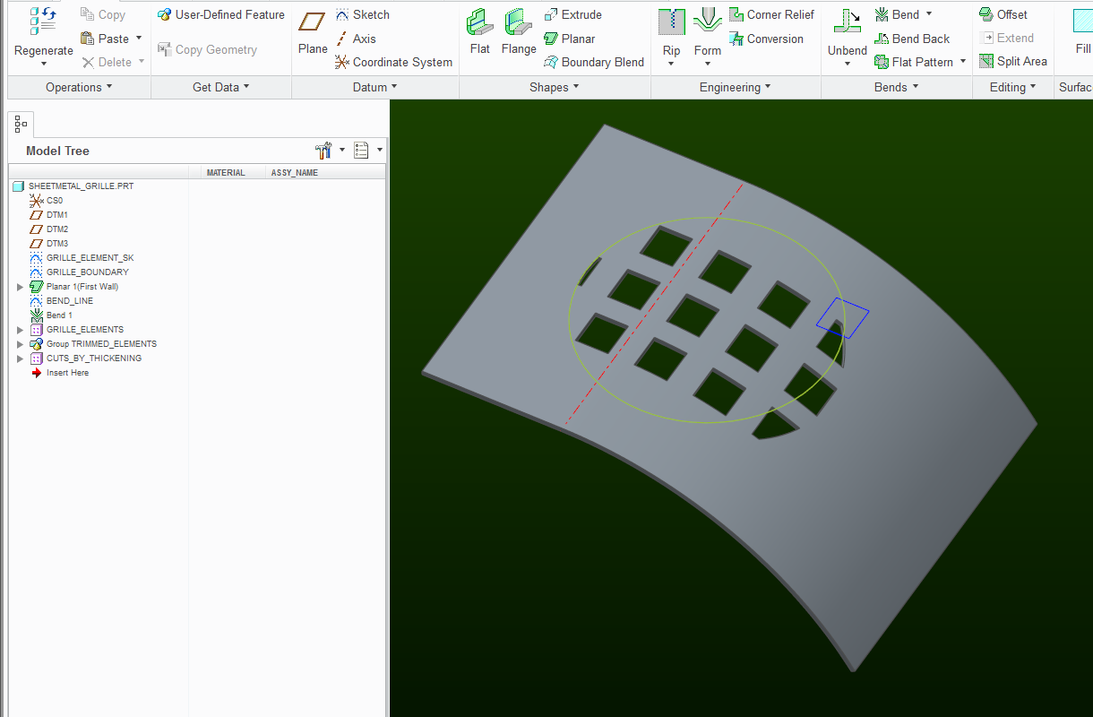
Examine the attached part file (Creo 2.0 model). In it, I cut a grille into a curved piece of sheet-metal.
This is how I went about it:
1) create a sketch GRILLE_ELEMENT_SK that defines the grille opening
2) create a sketch GRILLE_BOUNDARY that defines the boundary
3) use the fill command to turn GRILLE_ELEMENT_SK into a surface patch
4) pattern the surface patch to form some kind of a grid of patches
5) trim the patches at the boundary using the sketched circle curve. Obviously, with more holes this becomes a very tedious task.
So, I recommend this mapkey that executes the copy -> paste-special -> advanced ref. configuration sequence, using the currently selected feature as the template:
mapkey cv @MAPKEY_NAMECopies currently selected feature;\
@MAPKEY_LABELCopy and Paste Special (cv);\
~ Command `ProCmdEditCopy` ;~ Command `ProCmdEditPasteSpecial`
~ Activate `paste_special` `makecopyiesPB` 0;\
~ Activate `paste_special` `pastebyrefPB` 1;\
~ Activate `paste_special` `okPB`;

(in this manner, you just have to pick a trimmed patch, type cv, then select the next patch to be trimmed and OK!
6) Anyway, after all that, select the 1st patch in the pattern (important!) and thicken it - this should make a single-cut in your sheet-metal. Make sure you cut in the right direction. Also be aware of the tool's options that result in different ways the cut will be made.
7) Select the resulting thicken feature in the model-tree, right-click and select "Pattern". The reference pattern should be activated and the whole grille will be produced. It's a bit baffling how it remembers that some of these patches were trimmed, but it does...
Caveats: if anything in your design changes in a significant way, you will probably need to delete the last pattern and go through steps 5-7 again.
Also, you might want to do this all this grille-cutting before doing any bending / forming...
