Turn on suggestions
Auto-suggest helps you quickly narrow down your search results by suggesting possible matches as you type.
Showing results for
Turn on suggestions
Auto-suggest helps you quickly narrow down your search results by suggesting possible matches as you type.
Showing results for
- Community
- Creo+ and Creo Parametric
- 3D Part & Assembly Design
- how to develop this?
Options
- Subscribe to RSS Feed
- Mark Topic as New
- Mark Topic as Read
- Float this Topic for Current User
- Bookmark
- Subscribe
- Mute
- Printer Friendly Page
how to develop this?
Jul 25, 2014
07:45 AM
- Mark as New
- Bookmark
- Subscribe
- Mute
- Subscribe to RSS Feed
- Permalink
- Notify Moderator
Jul 25, 2014
07:45 AM
how to develop this?
1 ACCEPTED SOLUTION
Accepted Solutions
Jul 26, 2014
03:17 AM
- Mark as New
- Bookmark
- Subscribe
- Mute
- Subscribe to RSS Feed
- Permalink
- Notify Moderator
Jul 26, 2014
03:17 AM
And if the facets are not desirable... and you want a true round top, this was the best I could come up with:
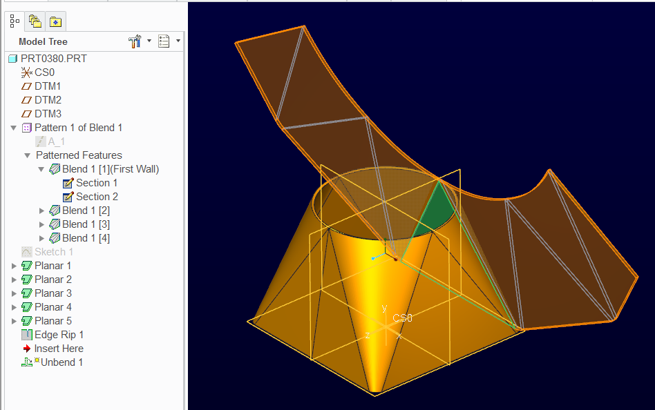
The corners are blends, and the planar features are the flat triangles.
Did you want the Creo 2 part of either of these?
49 REPLIES 49
Jul 25, 2014
11:39 PM
- Mark as New
- Bookmark
- Subscribe
- Mute
- Subscribe to RSS Feed
- Permalink
- Notify Moderator
Jul 25, 2014
11:39 PM
has anybody tried this?
i was surprised when i was not able to make this with boundary blend.
Jul 26, 2014
03:07 AM
- Mark as New
- Bookmark
- Subscribe
- Mute
- Subscribe to RSS Feed
- Permalink
- Notify Moderator
Jul 26, 2014
03:07 AM
We did have this discussion before. It can be done with sheetmetal.
Jul 26, 2014
03:17 AM
- Mark as New
- Bookmark
- Subscribe
- Mute
- Subscribe to RSS Feed
- Permalink
- Notify Moderator
Jul 26, 2014
03:17 AM
And if the facets are not desirable... and you want a true round top, this was the best I could come up with:
The corners are blends, and the planar features are the flat triangles.
Did you want the Creo 2 part of either of these?
Jul 26, 2014
03:40 AM
- Mark as New
- Bookmark
- Subscribe
- Mute
- Subscribe to RSS Feed
- Permalink
- Notify Moderator
Jul 26, 2014
03:40 AM
are there any sharp corners?
Jul 26, 2014
03:47 AM
- Mark as New
- Bookmark
- Subscribe
- Mute
- Subscribe to RSS Feed
- Permalink
- Notify Moderator
Jul 26, 2014
03:47 AM
One of the challenges was to get a sharp point at the top for the true circle. That is the reason for the high feature count. Of course, there is still the bend radius.
Follow up work with the part also showed it very difficult to develop additional features on the edges. It was simply stubborn, like so many things PTC.
Jul 26, 2014
03:41 AM
- Mark as New
- Bookmark
- Subscribe
- Mute
- Subscribe to RSS Feed
- Permalink
- Notify Moderator
Jul 26, 2014
03:41 AM
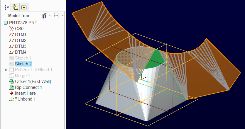
The problem with your model appears to be in the boundary blend definitions. If you flatten just one of the triangle, and place a point along a long edge, you will see the end of the sheet is no longer tied to the point at the square. Lack of tangency control can do this.
Using the same curves, I made single blend with control points. Couldn't get a full single feature, but over half defined properly. The extrude is squaring-up trim. A point along the straight edge allowed for a reliable flatten quilt.
Jul 26, 2014
03:53 AM
- Mark as New
- Bookmark
- Subscribe
- Mute
- Subscribe to RSS Feed
- Permalink
- Notify Moderator
Jul 26, 2014
03:53 AM
thankyou Antonius. if you could upload the creo 2 files?
Jul 26, 2014
03:56 AM
- Mark as New
- Bookmark
- Subscribe
- Mute
- Subscribe to RSS Feed
- Permalink
- Notify Moderator
Jul 26, 2014
03:56 AM
See if these work for you. Just unbend prt0380.prt
Jul 26, 2014
04:01 AM
- Mark as New
- Bookmark
- Subscribe
- Mute
- Subscribe to RSS Feed
- Permalink
- Notify Moderator
Jul 26, 2014
04:01 AM
the half that you have flattened (flatten quilt) ..are the end edges flat?
Jul 26, 2014
04:22 AM
- Mark as New
- Bookmark
- Subscribe
- Mute
- Subscribe to RSS Feed
- Permalink
- Notify Moderator
Jul 26, 2014
04:22 AM
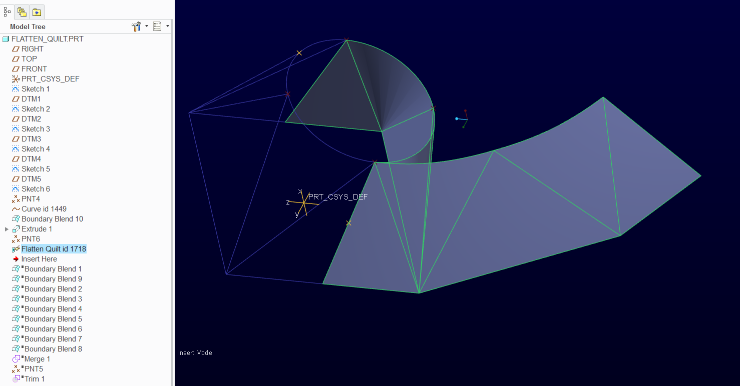
I am going to assume so. I am working the boundary blend with control points. I cannot get a 4-arc circle to join completely with the 4 straight sides, but I can get 3 to work. So I have to trim the boundary blend. But those are properly developed and tangent faces prior t the trim.
Jul 26, 2014
04:41 AM
- Mark as New
- Bookmark
- Subscribe
- Mute
- Subscribe to RSS Feed
- Permalink
- Notify Moderator
Jul 26, 2014
04:41 AM
strange when i use a plane to trim the surface and then flatten the edges are not flat.
but when i cut with extrude and flatten the edges are flat.
Jul 26, 2014
04:47 AM
- Mark as New
- Bookmark
- Subscribe
- Mute
- Subscribe to RSS Feed
- Permalink
- Notify Moderator
Jul 26, 2014
04:47 AM
sorry sorry..my mistake...
the one with control points and one boundary blend gives straight edges.
the one with multiple boundary blend does not give straight edges.
Jul 26, 2014
01:14 PM
- Mark as New
- Bookmark
- Subscribe
- Mute
- Subscribe to RSS Feed
- Permalink
- Notify Moderator
Jul 26, 2014
01:14 PM
I suppose you could create the flat triangles with Fill feature.
That way you have something to make the corner boundary blend features tangent to.
I always forget about simply trimming suffaces.
Oh so many cats to skin 
Jul 26, 2014
01:20 PM
- Mark as New
- Bookmark
- Subscribe
- Mute
- Subscribe to RSS Feed
- Permalink
- Notify Moderator
Jul 26, 2014
01:20 PM
And there is a funny artifact in the flattened quilt. If you sketch on that flat surface, the arc-edge should be a perfect circle. It is not, however. Even in sheetmetal, a small "dip" between control points can be detected. I suspect you want to correct this in the flattened quilt state.
Jul 26, 2014
11:14 PM
- Mark as New
- Bookmark
- Subscribe
- Mute
- Subscribe to RSS Feed
- Permalink
- Notify Moderator
Jul 26, 2014
11:14 PM
The more I work with this geometry, more I see development throwing in random "factors" depending on the core geometry. In this case, I added fills with tangent boundary blends on the corners. When this is flattened, it adds radii at the corners and the round is "tighter".
For this object, no deformation is required, yet it puts it in there... and arbitrarily at that.
Jul 26, 2014
11:47 PM
- Mark as New
- Bookmark
- Subscribe
- Mute
- Subscribe to RSS Feed
- Permalink
- Notify Moderator
Jul 26, 2014
11:47 PM
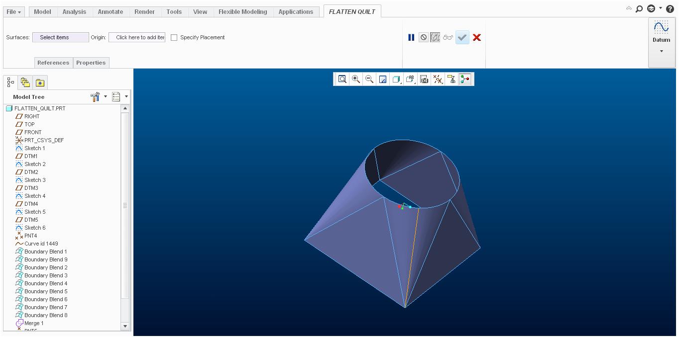
I tried with the new flatten quilt tool..but still it does not flatten the complete surface.
I thought it would be able to handle that.
just enable "new_flatten_quilt" in config.pro
Jul 27, 2014
12:08 AM
- Mark as New
- Bookmark
- Subscribe
- Mute
- Subscribe to RSS Feed
- Permalink
- Notify Moderator
Jul 27, 2014
12:08 AM
Hah! New Creo 3.0 references are starting to drive me nuts already.
it has trouble with the full surface not matter what you do.
In the previous example, the fact that the geometry is not consistent depending on how it is built is bothersome.
I did figure out why the top edges are not round. It is simply the geometry. But I still haven't found the math that should be driving it. However, it makes a mess of thickened walls just like it does in sheetmetal.
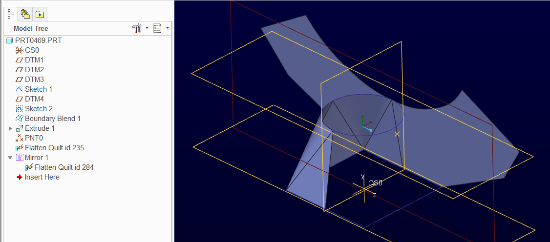
Mirror is working fine with the flatten quilt. You can even drive a flatten-quilt deformation (re-form) with features on the mirrored flatten feature.
What exactly are you trying to accomplish?
Jul 27, 2014
12:22 AM
- Mark as New
- Bookmark
- Subscribe
- Mute
- Subscribe to RSS Feed
- Permalink
- Notify Moderator
Jul 27, 2014
12:22 AM
it will basically be a section of sheetmetal assembly to be used to fill spices in pouches.
i would need the development to cut the shape on the sheetmetal.
one more different result i guess..have a look..if you have time.
Jul 27, 2014
12:45 AM
- Mark as New
- Bookmark
- Subscribe
- Mute
- Subscribe to RSS Feed
- Permalink
- Notify Moderator
Jul 27, 2014
12:45 AM
I see... then yes, the sheetmetal version will probably work best for you.
I cannot seem to modify the 2 flatten quilts in my Creo 2.0 as you have them defined.
Is this a Creo 3.0 file or WF5/Elements Pro? It opens in Creo 2.0.
I have noticed that flatten quilt builds a "plane" from the edge at or near the point used in the flatten quilt. If it is a good straight edge, it does pretty well. In the case of the fill/boundary blends, however, it takes some serious liberties with the tangent merge along the two surfaces.
Have you considered just forming a round tube with a square die 
The attached file is working pretty well. Is the same as the previous with the garbage removed and to re-forming.
Jul 27, 2014
12:51 AM
- Mark as New
- Bookmark
- Subscribe
- Mute
- Subscribe to RSS Feed
- Permalink
- Notify Moderator
Jul 27, 2014
12:51 AM
initially i made it in creo elements/pro 5.0..but the latest one i uploaded is in creo 2.0.
i do not have creo 3.0...they stopped our maintenance mid-way..how cruel is that. 
Jul 27, 2014
12:55 AM
- Mark as New
- Bookmark
- Subscribe
- Mute
- Subscribe to RSS Feed
- Permalink
- Notify Moderator
Jul 27, 2014
12:55 AM
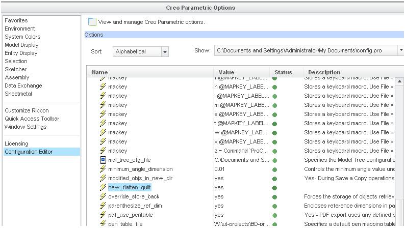
So where is this new_flatten_quilt option?
Seriously, that last file just locked me out of doing anything with those two features.
Jul 27, 2014
12:59 AM
- Mark as New
- Bookmark
- Subscribe
- Mute
- Subscribe to RSS Feed
- Permalink
- Notify Moderator
Jul 27, 2014
12:59 AM
in the add option just enter "new_flatten_quilt" the ok option will be activated. this is in creo 2.0
Jul 27, 2014
01:05 AM
- Mark as New
- Bookmark
- Subscribe
- Mute
- Subscribe to RSS Feed
- Permalink
- Notify Moderator
Jul 27, 2014
01:05 AM
You must have a style option or something... I get nothing 
Jul 27, 2014
01:21 AM
- Mark as New
- Bookmark
- Subscribe
- Mute
- Subscribe to RSS Feed
- Permalink
- Notify Moderator
Jul 27, 2014
01:21 AM
you have to add it in the config.pro.
its a hidden option
Jul 27, 2014
02:09 AM
- Mark as New
- Bookmark
- Subscribe
- Mute
- Subscribe to RSS Feed
- Permalink
- Notify Moderator
Jul 27, 2014
02:09 AM
Okay, finally got it to go to the new UI (was missing the YES/NO). Not impressed!
Okay, this fails miserably with fills and merged boundary blends in the corners.
I can get a consistent flat state with 1/2 the part when the original was made with the boundary blend using control points as a single object. It is very tedious entering those points and it fails every time I enter the last pair.
Jul 27, 2014
02:58 AM
- Mark as New
- Bookmark
- Subscribe
- Mute
- Subscribe to RSS Feed
- Permalink
- Notify Moderator
Jul 27, 2014
02:58 AM
hate to say this..but it was a piece of cake on CATIA.
the boundary blend and the flatten both of them.
and CATIA was able to flatten the complete quilt..
Jul 27, 2014
03:13 AM
- Mark as New
- Bookmark
- Subscribe
- Mute
- Subscribe to RSS Feed
- Permalink
- Notify Moderator
Jul 27, 2014
03:13 AM
PTC should really look at some of these saga challenges we come up with.
Including recording the time it takes an engineer to actually do the challenge, and not find some obscure work-around or tell us that this is not how -anyone- would ever do -anything-.
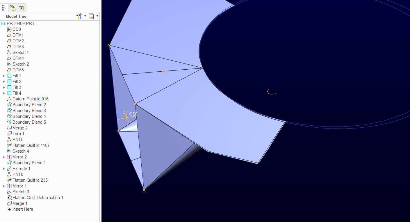
Finally got it using a two-stage flatten process. I thought I had it in one, but it left a triangle behind. For some reason, it doesn't recognize the split surface and maintain the rest as a single quilt.
I turned off the hidden flatten quilt UI so others can use this without it enabled.
Jul 27, 2014
03:19 AM
- Mark as New
- Bookmark
- Subscribe
- Mute
- Subscribe to RSS Feed
- Permalink
- Notify Moderator
Jul 27, 2014
03:19 AM
PTC is like an Indian goverment office..they will only work if a lot of pressure is put on them..in this case a big customer asks them to put in some functionality..otherwise you have to do with what you have been given
Jul 27, 2014
03:26 AM
- Mark as New
- Bookmark
- Subscribe
- Mute
- Subscribe to RSS Feed
- Permalink
- Notify Moderator
Jul 27, 2014
03:26 AM
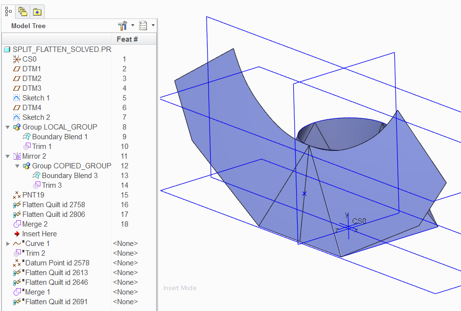
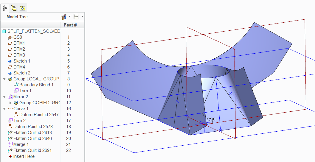
Of course, after the mirrored group, you can flatten each half and merge them.
But most importantly, the feature creation method creates a reliable result apparently with very little distortion.
The edge is still 220 and the arc length is within .001 of the original.
And it works well flatten-quilt deformation if you needed to add something in the flat state.