
Turn on suggestions
Auto-suggest helps you quickly narrow down your search results by suggesting possible matches as you type.
Showing results for
Turn on suggestions
Auto-suggest helps you quickly narrow down your search results by suggesting possible matches as you type.
Showing results for
Community Tip - Visit the PTCooler (the community lounge) to get to know your fellow community members and check out some of Dale's Friday Humor posts! X
- Community
- Creo+ and Creo Parametric
- 3D Part & Assembly Design
- how to roll this into a frustum of cone in proe sh...
Options
- Subscribe to RSS Feed
- Mark Topic as New
- Mark Topic as Read
- Float this Topic for Current User
- Bookmark
- Subscribe
- Mute
- Printer Friendly Page
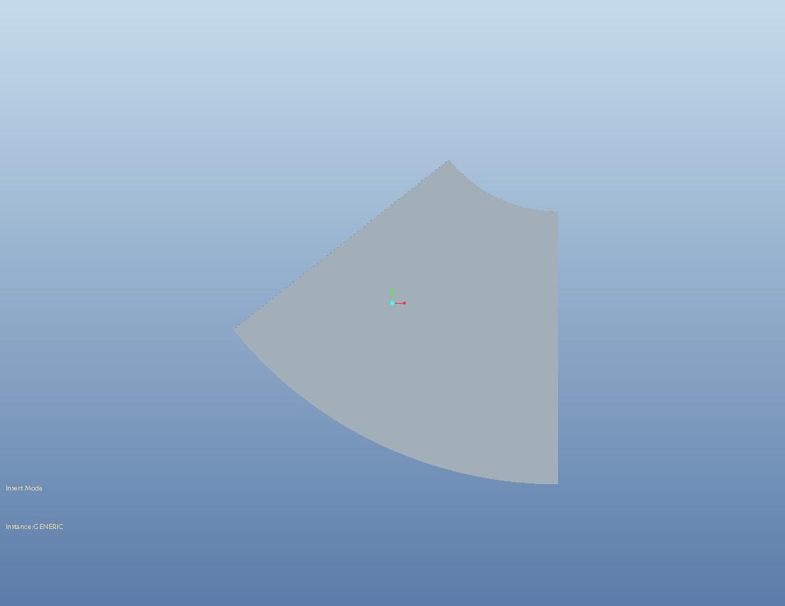
how to roll this into a frustum of cone in proe sheetmetal?
Sep 07, 2013
12:19 AM
- Mark as New
- Bookmark
- Subscribe
- Mute
- Subscribe to RSS Feed
- Permalink
- Notify Moderator
Sep 07, 2013
12:19 AM
how to roll this into a frustum of cone in proe sheetmetal?
This thread is inactive and closed by the PTC Community Management Team. If you would like to provide a reply and re-open this thread, please notify the moderator and reference the thread. You may also use "Start a topic" button to ask a new question. Please be sure to include what version of the PTC product you are using so another community member knowledgeable about your version may be able to assist.
Labels:
- Labels:
-
Sheet Metal Design
6 REPLIES 6
Sep 07, 2013
01:18 AM
- Mark as New
- Bookmark
- Subscribe
- Mute
- Subscribe to RSS Feed
- Permalink
- Notify Moderator
Sep 07, 2013
01:18 AM
I am going to suggest doing this backward... make the form and then unfold it.
See attached.
Sep 07, 2013
01:54 AM
- Mark as New
- Bookmark
- Subscribe
- Mute
- Subscribe to RSS Feed
- Permalink
- Notify Moderator
Sep 07, 2013
01:54 AM
Thanks Antonius.
I have used the same method. just wanted to know is there method to roll a flat sheet in Pro/sheetmetal?
Sep 07, 2013
02:13 AM
- Mark as New
- Bookmark
- Subscribe
- Mute
- Subscribe to RSS Feed
- Permalink
- Notify Moderator
Sep 07, 2013
02:13 AM
I haven't found a way to make a variable bend radius. Hopefully someone will show how its done.
Sep 07, 2013
08:01 AM
- Mark as New
- Bookmark
- Subscribe
- Mute
- Subscribe to RSS Feed
- Permalink
- Notify Moderator
Sep 07, 2013
08:01 AM
the problem is i have the cone development dimensions only..trying the reverse method..but they do not match with the development dimensions after i flatten the cone.
Sep 07, 2013
01:59 PM
- Mark as New
- Bookmark
- Subscribe
- Mute
- Subscribe to RSS Feed
- Permalink
- Notify Moderator
Sep 07, 2013
01:59 PM
I figured that was the case. It takes a bit of math to understand what the form would be folmed. Fortunately, and I haven't tried this yet, but there has to be a formula to get the angle of the edges to know the angle of the axis in relation to the cone center.
The problem is the stretch and crush (K-factor) . However, with the known K-Factor you can also interpolate the radius at several points to know what you need to use for an offset between the solid and the axis. Both radii sould be coincident if it is a regular cone, so you can work the radii position from the apex.
Once you match up the edges on an unfold operation, you can use the "master" to trim the smaller and larger circle on the ends. After a bend back, the edges will still match up and the ends will be correct.
Sep 13, 2013
09:33 AM
- Mark as New
- Bookmark
- Subscribe
- Mute
- Subscribe to RSS Feed
- Permalink
- Notify Moderator
Sep 13, 2013
09:33 AM
There is no function in Creo Parametric that allows to bend about an axis which is not parallel to the fix edge.
But as Antonius mentioned, it should be possible by some formula.
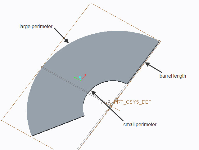
If you want to avoid mathematics, you can also use a simple construction approach by sketching two circles to correspond to the circular edges of the cylinder and a line to connects the two "orbits", which represents the fix edge when unbending (equal to the barrel length)
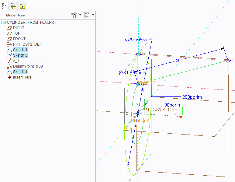
If you use perimeter dimensions in the sketches, you can simply enter the values measured from your flat geometry to drive the sketcher dimensions. This is because the edge lengths are the same in bend and unbend state.
The sketched line (Sketch4 in the picture) can then be used to generate the cylinder revolving about A_1.For solid geometry thicken the surface, depending on which edges you measured.
You may want to cover for stretch by applying to the measured dimensions as needed.
If you rip and unbend, you can control, whether the geometry is as expected.
