
Turn on suggestions
Auto-suggest helps you quickly narrow down your search results by suggesting possible matches as you type.
Showing results for
Turn on suggestions
Auto-suggest helps you quickly narrow down your search results by suggesting possible matches as you type.
Showing results for
Community Tip - You can subscribe to a forum, label or individual post and receive email notifications when someone posts a new topic or reply. Learn more! X
Options
- Subscribe to RSS Feed
- Mark Topic as New
- Mark Topic as Read
- Float this Topic for Current User
- Bookmark
- Subscribe
- Mute
- Printer Friendly Page
k factor
Nov 04, 2015
12:57 PM
- Mark as New
- Bookmark
- Subscribe
- Mute
- Subscribe to RSS Feed
- Permalink
- Notify Moderator
Nov 04, 2015
12:57 PM
k factor
hello
i want to solve a problem with flat pattern in creo
how it is best k factor for steel , for a very good sheetmetal in reality
i use k=0.5 but this factor do not reflect reality flat pattern, i need to make some corrections for a best flat
exist best ruls for optimizing flat pattern (right habits  )?
)?
is it somebody how corelate salvagnini and creo for best results without corrections?
please tell me a best k factor and important ruls in calculate developed lenght
tks
This thread is inactive and closed by the PTC Community Management Team. If you would like to provide a reply and re-open this thread, please notify the moderator and reference the thread. You may also use "Start a topic" button to ask a new question. Please be sure to include what version of the PTC product you are using so another community member knowledgeable about your version may be able to assist.
Solved! Go to Solution.
Labels:
- Labels:
-
General
1 ACCEPTED SOLUTION
Accepted Solutions
Dec 02, 2015
04:26 PM
- Mark as New
- Bookmark
- Subscribe
- Mute
- Subscribe to RSS Feed
- Permalink
- Notify Moderator
Dec 02, 2015
04:26 PM
Technically, a K factor of .5 should be in the middle to the developed length is simply the mean length along the center of the formed part.
The only variation you should see from one CAD package to another is when the inside bend radius is changed.
Otherwise, it is easy to measure with a sketch over the formed part.
Somewhere in the back of my mind I seem to recall testing this theory, and if I remember right, Creo came up with the right answer.
8 REPLIES 8
Nov 04, 2015
02:09 PM
- Mark as New
- Bookmark
- Subscribe
- Mute
- Subscribe to RSS Feed
- Permalink
- Notify Moderator
Nov 04, 2015
02:09 PM
The K-factor will vary depending on the actual material and the type of forming you are doing.
Where I used to work, we used 0.44 (Y Factor = 0.69115) and that worked out well for our processes.
Nov 04, 2015
02:56 PM
- Mark as New
- Bookmark
- Subscribe
- Mute
- Subscribe to RSS Feed
- Permalink
- Notify Moderator
Nov 04, 2015
02:56 PM
I did a test with a 'U" shaped part.
The 2 end flanges were 1.5" tall from the outside and there was 5" between the 2 outside walls.
Part thickness was 0.25" and the inside bend radius was 0.5"
With a Y-factor of .5 (Creo default) the flat pattern ws 7.0354" long.
With a Y-factor of .69115 (K-factor of .44) the flat pattern was 7.1312" long.
Reference pages explaining K-factor and Y-factor.
Nov 04, 2015
03:04 PM
- Mark as New
- Bookmark
- Subscribe
- Mute
- Subscribe to RSS Feed
- Permalink
- Notify Moderator
Nov 04, 2015
03:04 PM
Wow, that takes me back to the good old days (well, maybe tough old days) of hand calculating flat patterns. I designed much simpler parts then, because if I didn't, I had to figure out the flat pattern!!!
Nov 04, 2015
11:45 PM
- Mark as New
- Bookmark
- Subscribe
- Mute
- Subscribe to RSS Feed
- Permalink
- Notify Moderator
Nov 04, 2015
11:45 PM
I use the rule of thumb method... 60% stretch/40% crush... for simple sheet-metal forming.
There is more deviation for a give dye in the resulting inside bend radius. ...Or if the die is coining the bend.
Dec 02, 2015
04:04 PM
- Mark as New
- Bookmark
- Subscribe
- Mute
- Subscribe to RSS Feed
- Permalink
- Notify Moderator
Dec 02, 2015
04:04 PM
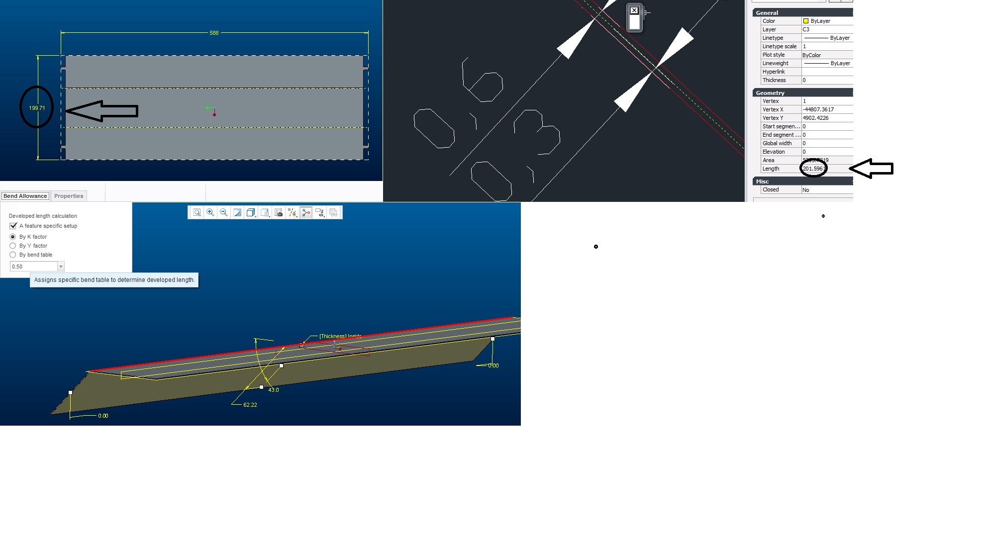
i have a problem and i don't understand
i have 0.6 thickness ,
i chose k=0,5 in creo , and 0.5 in other 2d program
but developed lenght is different what is the reason for this
was happened?
where i make mistakes?
tks in advance
Dec 02, 2015
04:13 PM
- Mark as New
- Bookmark
- Subscribe
- Mute
- Subscribe to RSS Feed
- Permalink
- Notify Moderator
Dec 02, 2015
04:13 PM
Creo uses the Y-factor by default while most other software uses the K-factor.
Did you set the sheetmetal module to use the K-factor value or just use the default value, which would be a Y-factor of .5?
Dec 02, 2015
04:25 PM
- Mark as New
- Bookmark
- Subscribe
- Mute
- Subscribe to RSS Feed
- Permalink
- Notify Moderator
Dec 02, 2015
04:25 PM
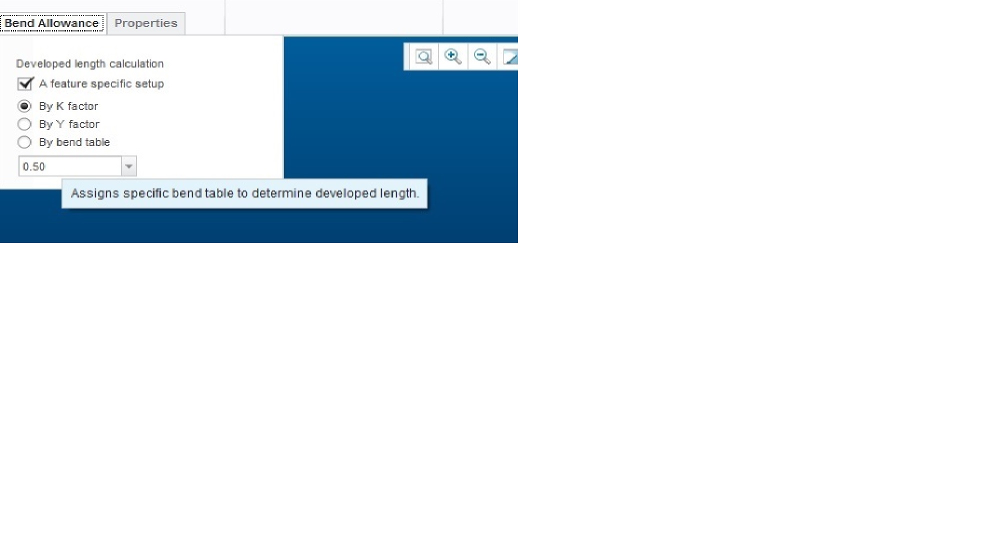
in pictures see k = 0.5
Dec 02, 2015
04:26 PM
- Mark as New
- Bookmark
- Subscribe
- Mute
- Subscribe to RSS Feed
- Permalink
- Notify Moderator
Dec 02, 2015
04:26 PM
Technically, a K factor of .5 should be in the middle to the developed length is simply the mean length along the center of the formed part.
The only variation you should see from one CAD package to another is when the inside bend radius is changed.
Otherwise, it is easy to measure with a sketch over the formed part.
Somewhere in the back of my mind I seem to recall testing this theory, and if I remember right, Creo came up with the right answer.
