
Turn on suggestions
Auto-suggest helps you quickly narrow down your search results by suggesting possible matches as you type.
Showing results for
Turn on suggestions
Auto-suggest helps you quickly narrow down your search results by suggesting possible matches as you type.
Showing results for
Community Tip - Did you get called away in the middle of writing a post? Don't worry you can find your unfinished post later in the Drafts section of your profile page. X
- Community
- Creo+ and Creo Parametric
- 3D Part & Assembly Design
- Creo 2.0: Cable to splice
Options
- Subscribe to RSS Feed
- Mark Topic as New
- Mark Topic as Read
- Float this Topic for Current User
- Bookmark
- Subscribe
- Mute
- Printer Friendly Page
Creo 2.0: Cable to splice
Sep 24, 2014
03:48 AM
- Mark as New
- Bookmark
- Subscribe
- Mute
- Subscribe to RSS Feed
- Permalink
- Notify Moderator
Sep 24, 2014
03:48 AM
Creo 2.0: Cable to splice
Hello,
I have 2 questions.
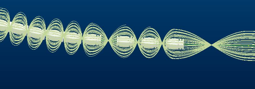
- Why do the wires cross each other like this? (The white squares are my splices) It doesn't really do anything, but it makes it hard to follow wires sometimes.
- And I have been playing around with my splices so that it will route everything automatically, but there are a few hick-ups.... like in the next picture.
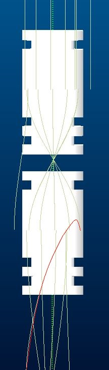
The red wire exits from the top of the splice, because of that I can't add it to a bundle. I know if I delete the routing and start over again. I can get it to work (for this splice) but here is the kicker. If I do the same for the splice underneath it, next in line of the routing, I get that same routing again for this splice. So I am not able to fix both. So I this a bug on creo 2.0 side of is my splice no good? I have about a 100 splice in my (small) network so it already takes a huge amount of time to reroute the network over and over again. The only thing I've found to "fix" it, is to delete the entry port of the splice and assign it manually.
I can use some help on how to implent a splice correctly (and what the model should have). The splice has only 1 pin, 2 c_sys's turn 180* from each other. At the moment, I instert the splice with "Assemble", assign my 2 C_SYS as "ENTRY_PORT", route an end of a network to each.
I do it like this because the instert splice doesn't want to work AT ALL for me. When I use that, all my wires come in at 1 end of the splice.
Thank you in advance,
With kind regards,
Ron
This thread is inactive and closed by the PTC Community Management Team. If you would like to provide a reply and re-open this thread, please notify the moderator and reference the thread. You may also use "Start a topic" button to ask a new question. Please be sure to include what version of the PTC product you are using so another community member knowledgeable about your version may be able to assist.
Labels:
- Labels:
-
Routed Syst. Design
7 REPLIES 7
Sep 30, 2014
07:15 AM
- Mark as New
- Bookmark
- Subscribe
- Mute
- Subscribe to RSS Feed
- Permalink
- Notify Moderator
Sep 30, 2014
07:15 AM
Hi Ron,
Regarding your first question:
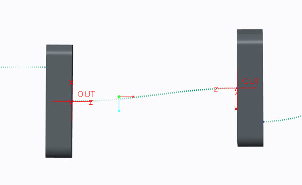
I think your problem is that C_SYS on your splices are in wrong orientation:
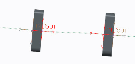
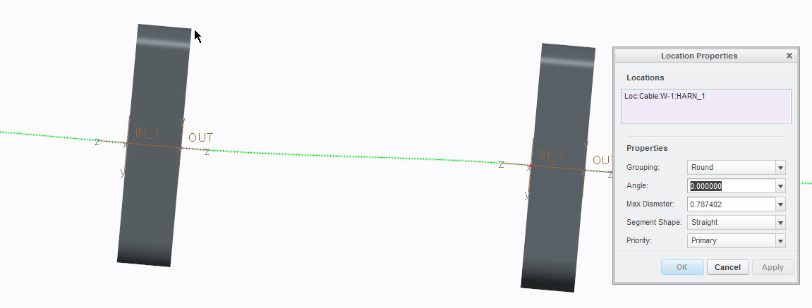
In the picture above you can see two C_SYS (highlighted in red) which are ENTRY ports of the splices, orientation of each C_SYS will define orientation of connected wires, therefore if Y-axis are not aligned in the same direction the wire will be forced to twist. What you need to do is to make sure that these C_SYS are aligned (which is easy since you used same model for all splices) or manually define angle for each problematic location using Location Properties dialog.
Regarding second question:
Wires will always connect to designated ENTRY PORT in Z-axis direction. In order to get desired routing make sure that wire is routed to ENTRY PORT’S C_SYS with Z-axis in direction shown below:
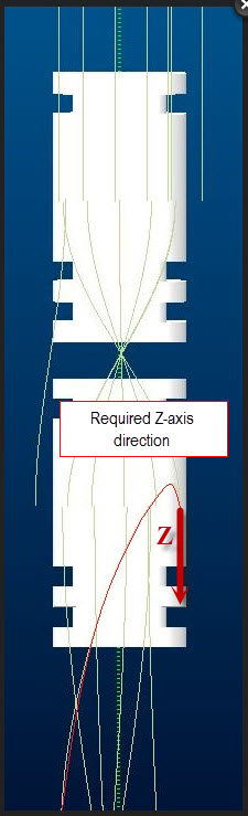
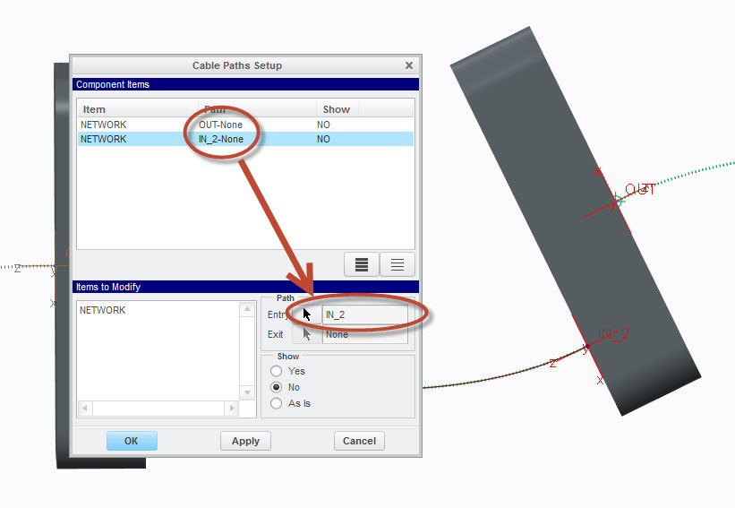
Your description of splice implementation seems to be correct. If you are willing to use “insert splice” you have to define path (Entry and Exit ports for splice) in Set Cable Path dialog both for network and wires.
Oct 03, 2014
01:30 AM
- Mark as New
- Bookmark
- Subscribe
- Mute
- Subscribe to RSS Feed
- Permalink
- Notify Moderator
Oct 03, 2014
01:30 AM
Thank you for your respons. My splice has to same design as yours, so the axis are alligned.
For the second part, i'll try it for our next harness.
Kind regards,
Ron
EDIT: I just made a small test harness. And I can only define an entry path but not an exit path. The exit option is blanked out.
When I define the entry path for both sides to the right Z-axis and try to route the wires, I need to select the entry port of the wire manually.
This is not really an option for the bigger harnesses.
Oct 06, 2014
09:06 AM
- Mark as New
- Bookmark
- Subscribe
- Mute
- Subscribe to RSS Feed
- Permalink
- Notify Moderator
Oct 06, 2014
09:06 AM
Hello Ron,
regarding the first question:
This looks as if the grouping / orientation of the location points are different, so the bunch of wires appears twisted. Try to redefine grouping or rotate the splices.
Gunter
Oct 07, 2014
03:35 AM
- Mark as New
- Bookmark
- Subscribe
- Mute
- Subscribe to RSS Feed
- Permalink
- Notify Moderator
Oct 07, 2014
03:35 AM
Hi Gunter,
Rotating the splices 180º helped with my wire problem... Now that one wire that was sticking in the wrong way is now routed correctly.
Ron
Oct 06, 2014
10:21 AM
- Mark as New
- Bookmark
- Subscribe
- Mute
- Subscribe to RSS Feed
- Permalink
- Notify Moderator
Oct 06, 2014
10:21 AM
Hi Ron,
Just to clarify my answer to the first question:
This is the C_SYS orientation that you probably have in your design:
This is C_SYS orientation that you should have in order to avoid cable twisting: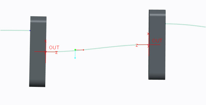
Regarding inserted splice workflow:
- Create a network
- Insert Component->Select desired Splice
- Use “Place Component” dialog to define entry port C_SYS and Cable location->OK
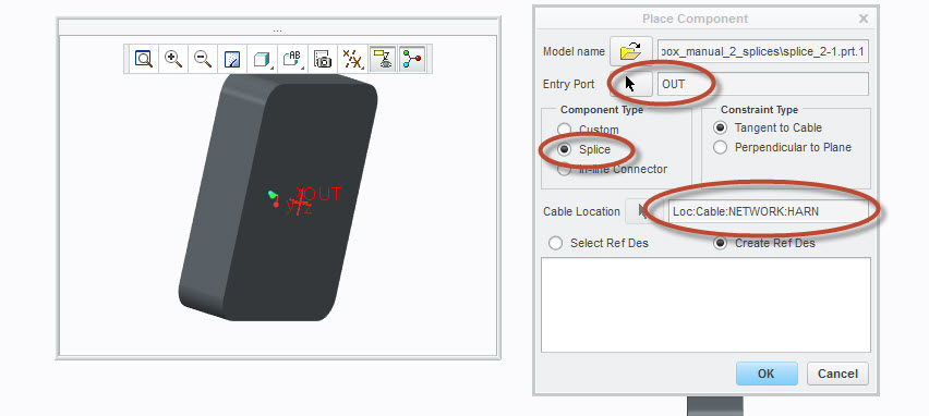
4. Use Cable Path Setup to define network’s entry ports
1. 5. Now you can route your wires via network.
Note that these two different types of splices: First one doesn't have internal portion so wire “inside splice” won't be take in to account when calculating total length.
The second one (with defined internal path) has internal portion so cable length inside the splice will be added to the total cable length.
Oct 07, 2014
03:44 AM
- Mark as New
- Bookmark
- Subscribe
- Mute
- Subscribe to RSS Feed
- Permalink
- Notify Moderator
Oct 07, 2014
03:44 AM
Hi Yakov,
This is how I them in my network, but I can fix the problem with turning the splice around 180º or deleting the entry part of my network to the splice and make a new network starting from the CSYS of the splice to the old network (only creating 2 points in that network).
These are still only a work-around, and it is starting to feel like cabling has alot of structural problems (bugs), with even more work-arounds. Will (some of) these be fixed with upgrading to Creo 3.0?
Kind regards,
Ron
Oct 07, 2014
04:17 AM
- Mark as New
- Bookmark
- Subscribe
- Mute
- Subscribe to RSS Feed
- Permalink
- Notify Moderator
Oct 07, 2014
04:17 AM
Ron,
We have made a lot of stabilization fixes in Creo 3.0, in case you have some specific issue, you can contact TS and report it.
Regards,
Yakov.
