
Turn on suggestions
Auto-suggest helps you quickly narrow down your search results by suggesting possible matches as you type.
Showing results for
Turn on suggestions
Auto-suggest helps you quickly narrow down your search results by suggesting possible matches as you type.
Showing results for
Community Tip - If community subscription notifications are filling up your inbox you can set up a daily digest and get all your notifications in a single email. X
- Community
- Creo+ and Creo Parametric
- Analysis
- Re: Gear Proper Meshing
Options
- Subscribe to RSS Feed
- Mark Topic as New
- Mark Topic as Read
- Float this Topic for Current User
- Bookmark
- Subscribe
- Mute
- Printer Friendly Page
Gear Proper Meshing
Jul 15, 2013
03:07 PM
- Mark as New
- Bookmark
- Subscribe
- Mute
- Subscribe to RSS Feed
- Permalink
- Notify Moderator
Jul 15, 2013
03:07 PM
Gear Proper Meshing
Hi all
I have a question regarding proper spur gear meshing.
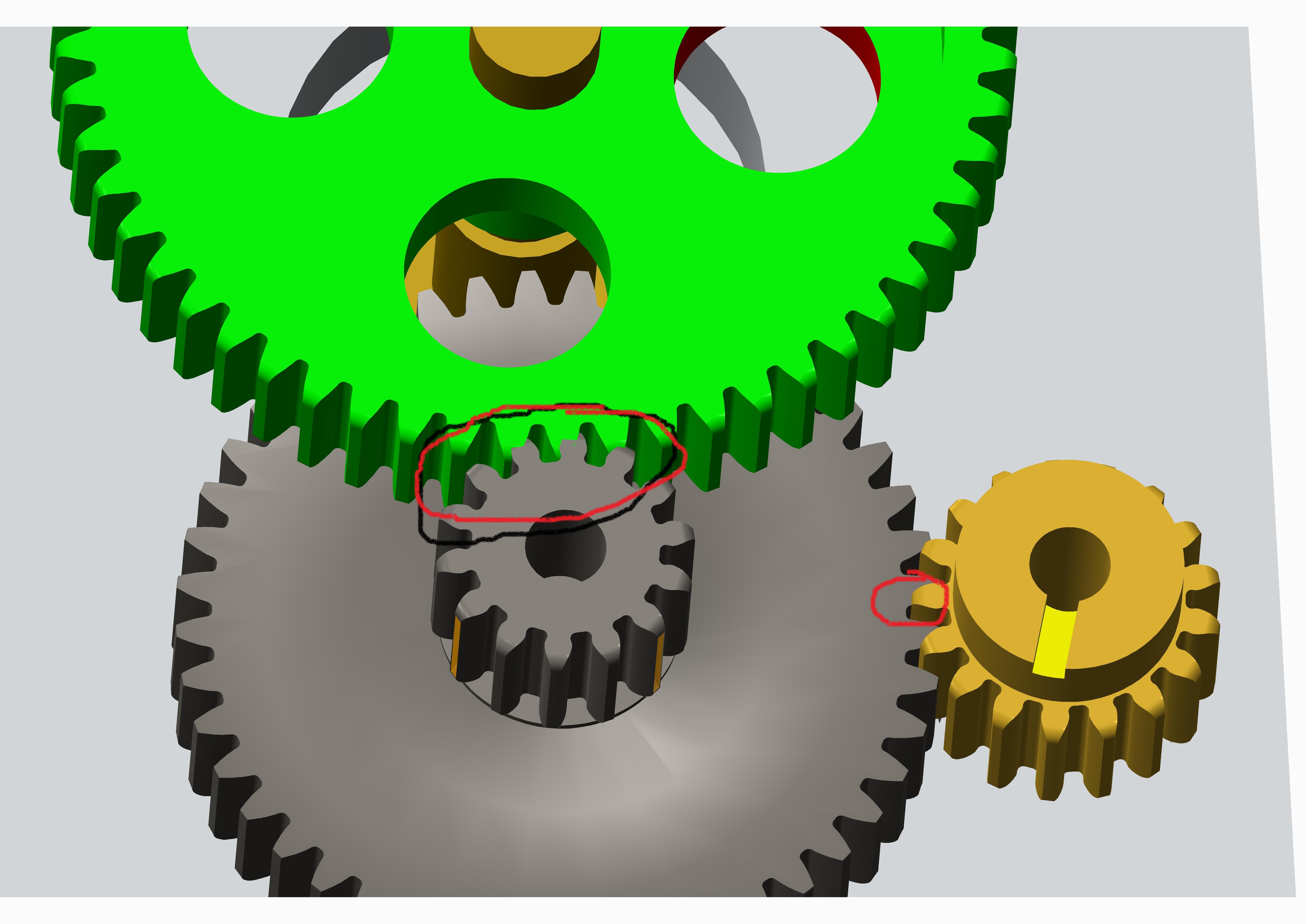
The two spur gear shown in the picture attached are meshed with the gear connection in mechanism by defining their pitch circle dia.
but when i move the mechanism with drag handle or it is moved by any other way they dont look like what gears should look like.
When they mesh they move into each other just like one is made of steel and the other is made of jelly.
Before meshing i create a came connection between mating gears so that their tooth faces are in contact.after that i delete it and then create a gear pair.
I also use the drag tool to align them.
The output velocity of the gear train is correct but i am worried about the impact forces which i need for its FEA Analysis.
I have read the help about creating dynamic gear pair.
Kindly help me if there is solution.
This thread is inactive and closed by the PTC Community Management Team. If you would like to provide a reply and re-open this thread, please notify the moderator and reference the thread. You may also use "Start a topic" button to ask a new question. Please be sure to include what version of the PTC product you are using so another community member knowledgeable about your version may be able to assist.
Labels:
- Labels:
-
General
5 REPLIES 5
Jul 15, 2013
04:38 PM
- Mark as New
- Bookmark
- Subscribe
- Mute
- Subscribe to RSS Feed
- Permalink
- Notify Moderator
Jul 15, 2013
04:38 PM
I'm going to suggest there may be a problem in the modeling of the gear itself. This should only take a quick calculation to confirm. The ratio of the number of teeth should be the same as the ratio of the two pitch diameters.
Jul 15, 2013
04:47 PM
- Mark as New
- Bookmark
- Subscribe
- Mute
- Subscribe to RSS Feed
- Permalink
- Notify Moderator
Jul 15, 2013
04:47 PM
Thanks Antonius Dirriwachter
yes as it is spur gear with module 1 so it its pitch dia and number of teeth are equal in value.Gear is modeled correctly.
Jul 15, 2013
04:56 PM
- Mark as New
- Bookmark
- Subscribe
- Mute
- Subscribe to RSS Feed
- Permalink
- Notify Moderator
Jul 15, 2013
04:56 PM
And when you confirm the 2 pitch diameter values for the Gears in Mechanism, they have the same ratio as the gear pair?
Did you uncover a S/W bug 
Jul 15, 2013
06:28 PM
- Mark as New
- Bookmark
- Subscribe
- Mute
- Subscribe to RSS Feed
- Permalink
- Notify Moderator
Jul 15, 2013
06:28 PM
yea.the second gear automatically picks the correct pitch circle dia which is it number of teeth.The green circles are tangent and are within the outer dia of each gear.it output velocity is according to the gear train ratio and is correct.
Jul 15, 2013
07:35 PM
- Mark as New
- Bookmark
- Subscribe
- Mute
- Subscribe to RSS Feed
- Permalink
- Notify Moderator
Jul 15, 2013
07:35 PM
In that case, it should just work right.
Care to submit this as a support case?
Announcements
Top Tags
