
Turn on suggestions
Auto-suggest helps you quickly narrow down your search results by suggesting possible matches as you type.
Showing results for
Turn on suggestions
Auto-suggest helps you quickly narrow down your search results by suggesting possible matches as you type.
Showing results for
Community Tip - Need to share some code when posting a question or reply? Make sure to use the "Insert code sample" menu option. Learn more! X
- Community
- Creo+ and Creo Parametric
- Analysis
- Reference pattern problem
Options
- Subscribe to RSS Feed
- Mark Topic as New
- Mark Topic as Read
- Float this Topic for Current User
- Bookmark
- Subscribe
- Mute
- Printer Friendly Page
Reference pattern problem
Aug 30, 2012
04:23 AM
- Mark as New
- Bookmark
- Subscribe
- Mute
- Subscribe to RSS Feed
- Permalink
- Notify Moderator
Aug 30, 2012
04:23 AM
Reference pattern problem
Hi all,
i wonder if anyone can explain the results i am getting with a reference pattern. i need the second pattern to reference the first pattern, so that if i change the number of holes or angular spacing in the first pattern, then the second pattern automatically updates. What i also require, is for the holes in the second pattern to remain normal to the revolved surface as the first pattern member does, the rest start to wander all over the place. This is what i need explaining, why is this happening? & is there a simple way to over come this? I have come up with a solution myself, but it means not using the reference pattern function, but instead having two separate patterns, & linking them by relation, but its long winded & not simple like i had hoped.
I have attached the part in the hope that someone may have an answer.
Regards
John
This thread is inactive and closed by the PTC Community Management Team. If you would like to provide a reply and re-open this thread, please notify the moderator and reference the thread. You may also use "Start a topic" button to ask a new question. Please be sure to include what version of the PTC product you are using so another community member knowledgeable about your version may be able to assist.
Labels:
- Labels:
-
General
10 REPLIES 10
Aug 30, 2012
04:53 AM
- Mark as New
- Bookmark
- Subscribe
- Mute
- Subscribe to RSS Feed
- Permalink
- Notify Moderator
Aug 30, 2012
04:53 AM
Hello John,
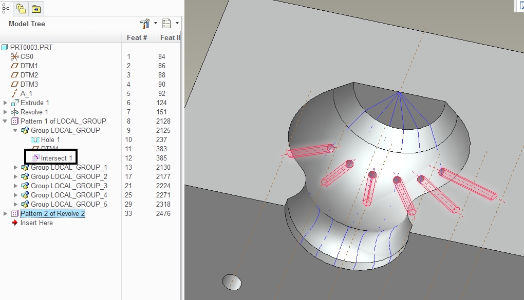
Just create the Intersect Feature in the first patterned group and it will work.
Aug 30, 2012
05:02 AM
- Mark as New
- Bookmark
- Subscribe
- Mute
- Subscribe to RSS Feed
- Permalink
- Notify Moderator
Aug 30, 2012
05:02 AM
Hi Antonio,
yes that just worked for me, the only disadvantage is i end up with more features than i really would like. Thank you for your reply.
Regards
John
Aug 30, 2012
08:21 AM
- Mark as New
- Bookmark
- Subscribe
- Mute
- Subscribe to RSS Feed
- Permalink
- Notify Moderator
Aug 30, 2012
08:21 AM
Hi John...
I think you're taking the wrong approach to this particular problem. I've remodeled the part with what is, in my humble opinion, a better technique.
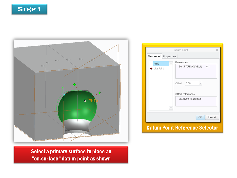
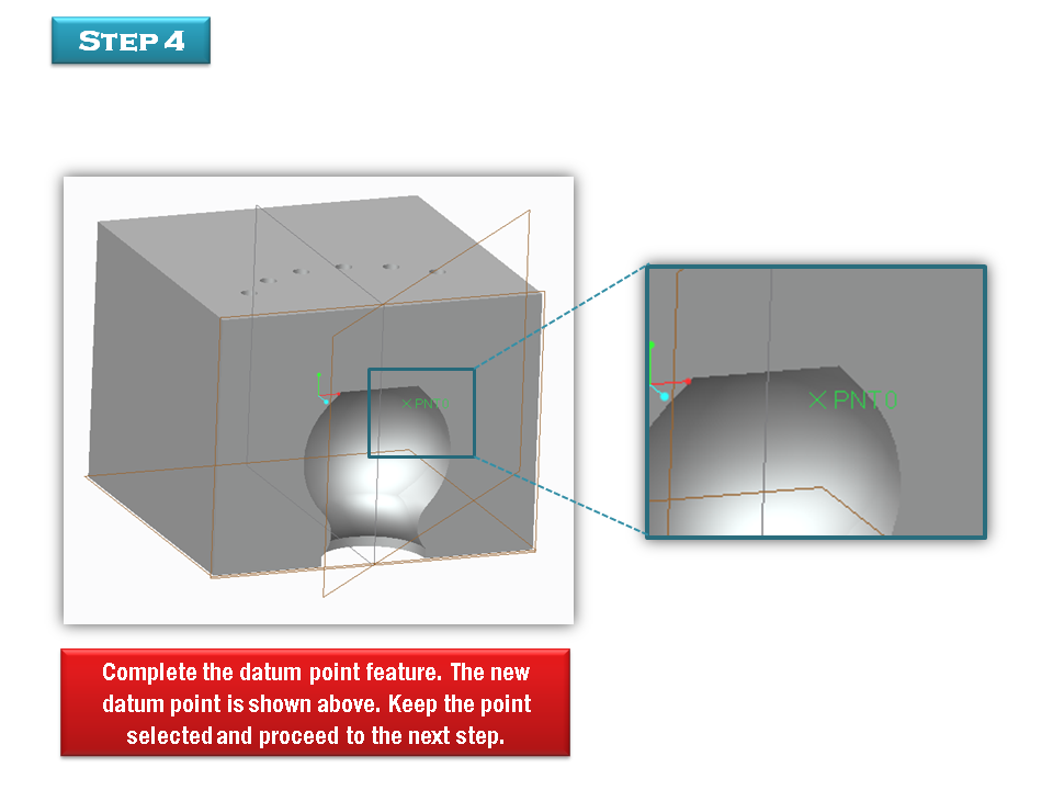
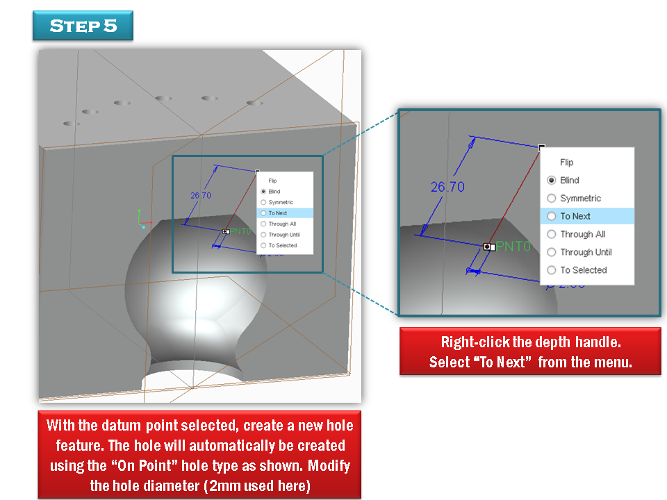
The key to the solution was your statement "What i also require, is for the holes in the second pattern to remain normal to the revolved surface". If you're creating holes and you want them to stay normal to some crazy surface, the first thing you should think it "On-Point Hole". This is a special hole type that doesn't appear on the hole type drop-down menu. The only way it appears is if you select a datum point as the first hole reference... but there's a catch, the datum point has to be an "on-surface" datum point.
Luckily this completely works for your situation.
I remodeled your part and attached it in Creo 2 format. I'm not sure which version you're running... it looked like Creo. I should've created it in Creo 1 but I wasn't thinking when I made it. If Creo 2 doesn't work for you and the instructions below don't help, let me know and I'll remodel in Creo 1.
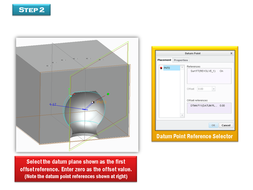
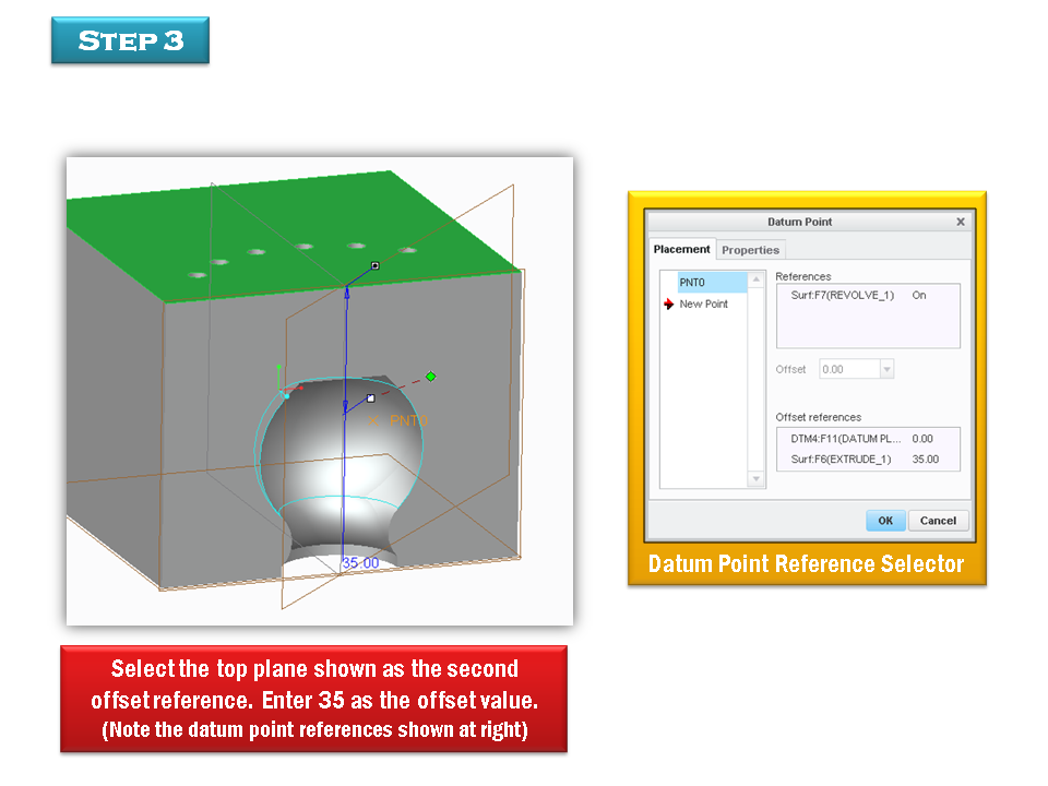
First... delete the intersection and the second pattern. Next, try this (click each slide for a larger image)...
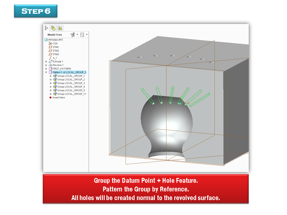
That should give you everything you needed including all original dimensions. You're able to use a simple hole rather than a revolved one. You're also able to eliminate the hole depth and allow Creo to control it automatically. You don't need the intersection... and you can easily hide the datum points by layer.
Hope this helps!
Thanks!
-Brian
Aug 30, 2012
11:01 AM
- Mark as New
- Bookmark
- Subscribe
- Mute
- Subscribe to RSS Feed
- Permalink
- Notify Moderator
Aug 30, 2012
11:01 AM
Hi Brian,
thank you for the reply, that indeed works & appears to work well, definitely food for thought. The only disadvantage i see with your approach is in the detailing, i would have to manually add the angular dimensions for all the normal holes, they require these in our shop. The model i posted was a very basic example, in reality the cavity is more complex & there are many more rows of holes, so creating all these angular dimensions would be a pain. FYI still using Creo elements/pro
Kind regards
John
Aug 30, 2012
12:17 PM
- Mark as New
- Bookmark
- Subscribe
- Mute
- Subscribe to RSS Feed
- Permalink
- Notify Moderator
Aug 30, 2012
12:17 PM
Ah! I'm using Creo Elements/Pro, too! I wish I'd have known...
You may look into creating the angular dimensions as annotations... and then just ref patterning them along with thre holes. This actually does work. I've done it before on other models. This way you get the reference dimensions you need while using the on-point method.
The cavity can be super complex... and you will always get a normal hole using the on-surface datum point. You can handle many rows of holes, too.
If you need examples, let me know!
Thanks!
-=Brian
Aug 31, 2012
03:07 AM
- Mark as New
- Bookmark
- Subscribe
- Mute
- Subscribe to RSS Feed
- Permalink
- Notify Moderator
Aug 31, 2012
03:07 AM
Hi Brian,
i am definitely going to look at implementing your approach. I want to do some trials for sure to see how thing pan out. At the risk of sounding like a complete novice, how would i create the annotations you suggest?
Regards
John
Aug 31, 2012
05:02 AM
- Mark as New
- Bookmark
- Subscribe
- Mute
- Subscribe to RSS Feed
- Permalink
- Notify Moderator
Aug 31, 2012
05:02 AM
Hi Brian,
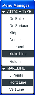
i have done some experimenting this morning, & creating these angled dimensions manually isn't as painful as i first thought. Because we have the datum points it gives me a reference through which i can "make line" in the attach type menu, & then select the axis of the hole, then create the dimension. I thought i was going to have to sketch a small 2d line & relate it to the drawing view, then create my dimension.
Would still like to know how to create the annotation you referred to. I had a bit of a play, & got every dimension except for the one i wanted.
Regards
John
Aug 31, 2012
03:34 PM
- Mark as New
- Bookmark
- Subscribe
- Mute
- Subscribe to RSS Feed
- Permalink
- Notify Moderator
Aug 31, 2012
03:34 PM
Hi John...
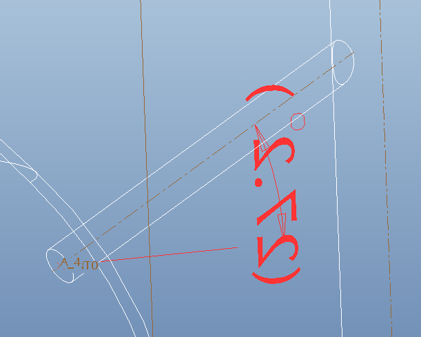
Check out the annotation below... is this the dimension you wanted?

This is a parametric reference dimension created right in the model. It travels with the holes. Also, I reworked the model so everything ran from one pattern. Here's the model tree...

You can obviously still do it the way you were before. For reference, I've included the part in Creo Elements/Pro (Wildfire 5) format. Take a look at the annotation. Here's a quick run-through of how I created this dimension...
- Select Insert->Annotations->Annotation Feature (You can use the new annotation icon, too)
- Select the Reference Dimension radio button and select OK.
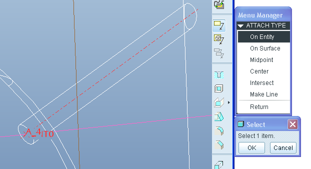
- Select Make Line->Horiz Line (as shown below) and select the Datum Point as a reference. You should see a horizontal line appear. If you see a vertical line even after you chose "Horiz Line", never fear. We can edit it later.
- Select On Entity from the menu and choose the Axis as shown (axis is in red), horizontal line shows up in purple on the image below.
- Press Middle Mouse Button to "Drop" the dimension as shown.
- Use Edit Orientation to achieve the correct placement and rotation for your dimension. It takes practice but within a few minutes, you;'ll be an expert.
Hope that helps!
Thanks!
-Brian
Sep 03, 2012
03:25 AM
- Mark as New
- Bookmark
- Subscribe
- Mute
- Subscribe to RSS Feed
- Permalink
- Notify Moderator
Sep 03, 2012
03:25 AM
Hi Brian,
thank you for all your help, i have decided to adopt your 'point on surface approach' for my master model, it appears to work well, time will tell but my testing was positive. As regards the angular dimension, i will stick with the manually created method, i will not have to keep creating them as they regenerated no problem.
Kind Regards
John
Sep 04, 2012
11:00 AM
- Mark as New
- Bookmark
- Subscribe
- Mute
- Subscribe to RSS Feed
- Permalink
- Notify Moderator
Sep 04, 2012
11:00 AM
Great news... thanks John!
Announcements
Top Tags
