
Turn on suggestions
Auto-suggest helps you quickly narrow down your search results by suggesting possible matches as you type.
Showing results for
Turn on suggestions
Auto-suggest helps you quickly narrow down your search results by suggesting possible matches as you type.
Showing results for
Community Tip - Learn all about PTC Community Badges. Engage with PTC and see how many you can earn! X
- Community
- Creo+ and Creo Parametric
- Analysis
- Twisting a plastic foil around a couple of cylinde...
Options
- Subscribe to RSS Feed
- Mark Topic as New
- Mark Topic as Read
- Float this Topic for Current User
- Bookmark
- Subscribe
- Mute
- Printer Friendly Page
Twisting a plastic foil around a couple of cylinders
Nov 24, 2015
05:24 AM
- Mark as New
- Bookmark
- Subscribe
- Mute
- Subscribe to RSS Feed
- Permalink
- Notify Moderator
Nov 24, 2015
05:24 AM
Twisting a plastic foil around a couple of cylinders
Hi!
I have a problem that I am working on. I need to get a plastic foil to twist 90 deg. from entering my system until leaving my system. For this I am intending to use some rollers to guide it from point A to B and getting the twist. I need to use this so that the twist doesnt affect the function.
Now, what I want to do is change the angles and positions of these rollers and basically see visually how the foil twists/moves according to these changes.
I've tried different methods without result.
I don't even know if this is possible to do in CREO but I ask to see if anyone has an idea/input to this.
BR/Stefan
This thread is inactive and closed by the PTC Community Management Team. If you would like to provide a reply and re-open this thread, please notify the moderator and reference the thread. You may also use "Start a topic" button to ask a new question. Please be sure to include what version of the PTC product you are using so another community member knowledgeable about your version may be able to assist.
Labels:
- Labels:
-
General
8 REPLIES 8
Nov 24, 2015
09:52 AM
- Mark as New
- Bookmark
- Subscribe
- Mute
- Subscribe to RSS Feed
- Permalink
- Notify Moderator
Nov 24, 2015
09:52 AM
Stefan,
please attach a picture to explain what you need to get.
MH
Martin Hanák
Nov 25, 2015
01:24 AM
- Mark as New
- Bookmark
- Subscribe
- Mute
- Subscribe to RSS Feed
- Permalink
- Notify Moderator
Nov 25, 2015
01:24 AM
Hi Martin,
Thanks for the reply.
I can not upload any images of the asm since it's company things, but I will just upload a quick paint image I made in order to explain.
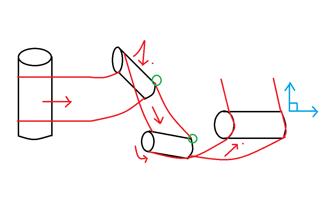
So there are 4 rollers on the picture. The red lines indicate the plastic foil and the arrows the direction it goes. The two outer rollers are where the foil enters and leaves, as you can see I need a 90 deg. angle between them. If I would drag the foil right between these there would be a twist that would obstruct the function of the system. Therefore I want to place the two rollers in the middle (green circles) in angles and positions so that it will be a "smooth" transition in the angles for the foil.
The rollers are solid parts and the two with green circles can be placed and rotated in the model. So what I want to do is to change the position of the rollers with green circles and see how the foil moves according to these changes.
Right now I have set up a mechanism model where I have divided the long foil in small parts to make it flexible. I have placed pin joints in three directions and put weld in between each foil-part. The model gets quite heavy and doesn't really behave as I want, it also falls through the "ground" rollers if I don't weld it onto a coordinate point on the surface.
So basically I would like some ideas if this is possible to do in a better way or so.
I've only worked with Creo tools for 3 months since I graduated so I realise I know very far from everything in CREO. That's why I went here. 
Hope this explained it better, have a nice day.
Nov 26, 2015
01:17 AM
- Mark as New
- Bookmark
- Subscribe
- Mute
- Subscribe to RSS Feed
- Permalink
- Notify Moderator
Nov 26, 2015
01:17 AM
Stefan,
I am sorry I have no idea how to solve your "situation"  .
.
MH
Martin Hanák
Nov 26, 2015
11:26 AM
- Mark as New
- Bookmark
- Subscribe
- Mute
- Subscribe to RSS Feed
- Permalink
- Notify Moderator
Nov 26, 2015
11:26 AM
Can you share a simplified assembly ?
Idea: Replace foil-part by a surface/curve ?
Nov 26, 2015
11:47 AM
- Mark as New
- Bookmark
- Subscribe
- Mute
- Subscribe to RSS Feed
- Permalink
- Notify Moderator
Nov 26, 2015
11:47 AM
Hi Steven
Something like this? It's just a quick solution to get the ball rolling, and it is unlikely to represent how the material would really behave.
David
Nov 27, 2015
01:59 AM
- Mark as New
- Bookmark
- Subscribe
- Mute
- Subscribe to RSS Feed
- Permalink
- Notify Moderator
Nov 27, 2015
01:59 AM
Thanks for your input guys!
Hi David,
I can't seem to open your file. Don't know what's wrong... It says 'CLINGFILM_ROLLERS' cannot be retrieved.
Hi Vincent,
I set up a model with two rollers, atm trying to get a foilmodel to wrap around the first roller. Straw_dyn assembly is basically just a rectangular part with a spherical bottom (for 3d-contact) connected to eachother with spheres with ball joints.
It doesn't really do what I intended, but it's one of my ideas.
The other is the suppressed straw_v2_dyn assembly where I am trying to make a band made of spheres connected with ball joints. The idea is to use them for 3D contact and then assemble the foil in the middle plane of the sphere...
Have a nice day,
Stefan
EDIT; There are no real material parameters set in my model, it's just for testing..,
Nov 27, 2015
07:44 AM
- Mark as New
- Bookmark
- Subscribe
- Mute
- Subscribe to RSS Feed
- Permalink
- Notify Moderator
Nov 27, 2015
07:44 AM
Hi
Agree with David, i think this is a good method ( screenshot from his prt )
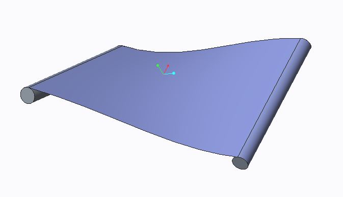
Stefan, you use Creo 2 ?
Nov 27, 2015
02:14 PM
- Mark as New
- Bookmark
- Subscribe
- Mute
- Subscribe to RSS Feed
- Permalink
- Notify Moderator
Nov 27, 2015
02:14 PM
There's no function to simulate the stretching of the film if it really twists.
Other than that I'd look at modeling this with sheetmetal, starting with a long flat ribbon and then marking bend lines where the rollers will contact the film. It would be an iterative process to fit the ribbon to a desired roller path.
The model David Marsland sent is in Creo 3; you appear to be using Creo 2 M130.
Announcements
Top Tags
