
Turn on suggestions
Auto-suggest helps you quickly narrow down your search results by suggesting possible matches as you type.
Showing results for
Turn on suggestions
Auto-suggest helps you quickly narrow down your search results by suggesting possible matches as you type.
Showing results for
Community Tip - When posting, your subject should be specific and summarize your question. Here are some additional tips on asking a great question. X
- Community
- Creo+ and Creo Parametric
- Analysis
- finding volume of voids
Options
- Subscribe to RSS Feed
- Mark Topic as New
- Mark Topic as Read
- Float this Topic for Current User
- Bookmark
- Subscribe
- Mute
- Printer Friendly Page
finding volume of voids
Jan 14, 2016
05:36 AM
- Mark as New
- Bookmark
- Subscribe
- Mute
- Subscribe to RSS Feed
- Permalink
- Notify Moderator
Jan 14, 2016
05:36 AM
finding volume of voids
Hi All,
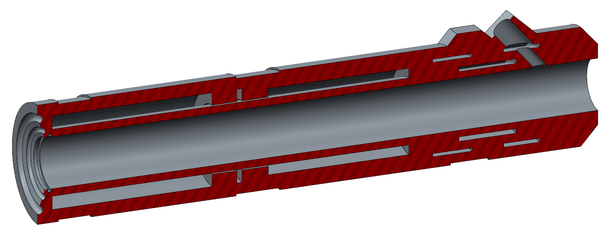
Attached is a shot of a cross section of a pipe assembly. Fluid enters the assembly via a port (item 303/ 304, to the right of the screen) and fills up all the un-hatched parts (some are too small to see.
I'm wanting to know what is the best way to find the volume of all the voids/ empty spaces in the assembly. If there is a function in Creo or if someone has a clever long way round. It does have to be the exact amount in these certain spaces.
Any help much appreciated!!
This thread is inactive and closed by the PTC Community Management Team. If you would like to provide a reply and re-open this thread, please notify the moderator and reference the thread. You may also use "Start a topic" button to ask a new question. Please be sure to include what version of the PTC product you are using so another community member knowledgeable about your version may be able to assist.
Labels:
- Labels:
-
General
12 REPLIES 12
Jan 14, 2016
07:19 AM
- Mark as New
- Bookmark
- Subscribe
- Mute
- Subscribe to RSS Feed
- Permalink
- Notify Moderator
Jan 14, 2016
07:19 AM
Since I am all about Old School, I would:
Export your parts as a surface using Copy Solid Surfaces.
Import those surfaces in and delete all the surfaces not comprising the volumes you want to measure
Create surfaces, extend boundaries, merge surfaces etc... to get enclosed volumes that you want.
Measure away.
Some young clickety clickers out there might suggest doing simple merges within the assembly of all your parts. But my guess is you have some slip fits and/or slight gaps that model accuracy issues might choke on. My suggestion is if it's important enough to do...do it in an explicit manner that you know will give you an explicit result.
Jan 14, 2016
07:21 AM
- Mark as New
- Bookmark
- Subscribe
- Mute
- Subscribe to RSS Feed
- Permalink
- Notify Moderator
Jan 14, 2016
07:21 AM
...clickety clickers... LOL!
Jan 14, 2016
01:21 PM
- Mark as New
- Bookmark
- Subscribe
- Mute
- Subscribe to RSS Feed
- Permalink
- Notify Moderator
Jan 14, 2016
01:21 PM
Hi Daryl,
I'm not young anymore, but do prefer to first attempt a Shrinkwrap > Merged Solid (no hole filling), and use the result to copy the internal surfaces using the Seed/Bound technique. (It might be necessary to "condition" the assembly, to ensure no unintended gaps/clearances, but it normally doesn't take long.
Regards,
Terry
Jan 15, 2016
04:08 AM
- Mark as New
- Bookmark
- Subscribe
- Mute
- Subscribe to RSS Feed
- Permalink
- Notify Moderator
Jan 15, 2016
04:08 AM
Terry's approach was roughly what first sprang to mind for me - seed-and-boundary selection of the surfaces seems like by far the easiest approach.
It just requires the internal volume to be made completely watertight...
Jan 14, 2016
06:12 PM
- Mark as New
- Bookmark
- Subscribe
- Mute
- Subscribe to RSS Feed
- Permalink
- Notify Moderator
Jan 14, 2016
06:12 PM
Here's a different approach: Instead of directly measuring the void, try calculating the difference in solid volume between your assembly and a space claim model. You'd have to make the space claim model, but it would only have to consist of the few and relatively simple external surfaces with some patches in order to solidify.
V_spaceclaim - V_assembly = V_void
Jan 15, 2016
04:04 AM
- Mark as New
- Bookmark
- Subscribe
- Mute
- Subscribe to RSS Feed
- Permalink
- Notify Moderator
Jan 15, 2016
04:04 AM
Could you elaborate on this "space claim" model Andrew?
Thanks!
Jan 15, 2016
08:58 AM
- Mark as New
- Bookmark
- Subscribe
- Mute
- Subscribe to RSS Feed
- Permalink
- Notify Moderator
Jan 15, 2016
08:58 AM
Daryl,
If I may be so bold....
The "Space Claim" approach...(I.E Old School Boolean Difference) means to create an oversized block and embed your "parts" into it within an assembly and then "cut out" those parts from the block. Thus giving you a "Space Claim". Kind of like creating a mold. The challenge with this, taking into account all the nooks and crannies I can see in your section is going to be tough. Not impossible...just tough.
I am not 100% sure how to pull this of with a ShrinkWrap either. Meaning, you still have to capture the "volume" and I would be at least one of your parts would result in an inverted surface somewhere when you go to capture the "volume". I may be wrong....but I think there is a good chance it will not merge properly later on.
I still believe explicit is the way to go. But then again...I'm Old School. And you know what they say about Old School...

Jan 15, 2016
12:27 PM
- Mark as New
- Bookmark
- Subscribe
- Mute
- Subscribe to RSS Feed
- Permalink
- Notify Moderator
Jan 15, 2016
12:27 PM
Maybe "space claim" was the wrong term to use. An envelope of your assembly is more like what I had in mind.
Here's a half baked recreation of your part (just a .prt, pretend it's an assembly). Its solid volume is 19E6 mm^3.
And here's an envelope/"space claim" of the above part. It's made from copy geom outside surfaces (seed & boundary collection) with open holes closed off then solidified. Its solid volume is 12E6 mm^3.
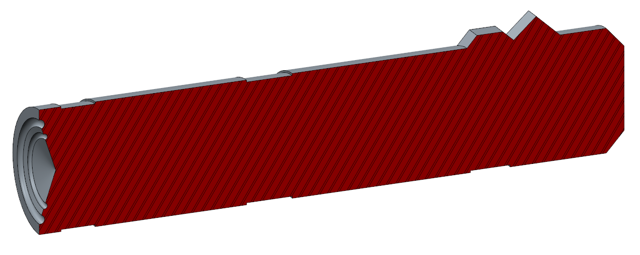
V_envelope - V_assembly = V_voids
19E6 - 12E6 = 7E6 mm^3
Jan 15, 2016
02:02 PM
- Mark as New
- Bookmark
- Subscribe
- Mute
- Subscribe to RSS Feed
- Permalink
- Notify Moderator
Jan 15, 2016
02:02 PM
Andrew,
Beautiful method and it works beautifully...using a single part without any interferences in the "volume" needed. Daryl's assembly looks like it may have some designed in Slip Fit/Press Fit that would need to be resolved. I am not discounting your method...it just would not give Daryl the Clickety-Click result as it's being described as.
No Flame intended....ever.
Jan 17, 2016
08:42 PM
- Mark as New
- Bookmark
- Subscribe
- Mute
- Subscribe to RSS Feed
- Permalink
- Notify Moderator
Jan 17, 2016
08:42 PM
You could use merge. Not overly automated but I've used it in a pinch.
The beauty is that you are not manipulating the "master" model. You just create a billet part that you subtract the solid volume from.
The billet could be driven by the master, or the outside can be cut away to reveal the inner volume (now solid).
Should remain parametric with due diligence on design revision monitoring.
Jan 18, 2016
04:14 AM
- Mark as New
- Bookmark
- Subscribe
- Mute
- Subscribe to RSS Feed
- Permalink
- Notify Moderator
Jan 18, 2016
04:14 AM
Thanks all, in the moment I exported to dxf, deleted what I didn't need in Autocad, then imported what was left back to Creo and revolved. It was a little messy but I had to get moving. I look forward to trying out you're idea the next time this comes up . . . and it will!
Thanks again, much appreciated!
Nov 18, 2016
07:04 PM
- Mark as New
- Bookmark
- Subscribe
- Mute
- Subscribe to RSS Feed
- Permalink
- Notify Moderator
Nov 18, 2016
07:04 PM
I didn't realize you only needed the entire volume, not just the volume in a cavity.
You can create datum curves from an existing cross section. look in the drop-down under Datum features.
If you create a revolve feature on the same cutting plane, you can copy the datum curves using Project in sketcher.
That would have solved this particular instance with accuracy and simplicity.
Announcements
Top Tags
