
Turn on suggestions
Auto-suggest helps you quickly narrow down your search results by suggesting possible matches as you type.
Showing results for
Turn on suggestions
Auto-suggest helps you quickly narrow down your search results by suggesting possible matches as you type.
Showing results for
- Community
- Creo+ and Creo Parametric
- Analysis
- mechanisms, trace curves and designing the largest...
Options
- Subscribe to RSS Feed
- Mark Topic as New
- Mark Topic as Read
- Float this Topic for Current User
- Bookmark
- Subscribe
- Mute
- Printer Friendly Page
mechanisms, trace curves and designing the largest parts...
Nov 29, 2010
01:26 PM
- Mark as New
- Bookmark
- Subscribe
- Mute
- Subscribe to RSS Feed
- Permalink
- Notify Moderator
Nov 29, 2010
01:26 PM
mechanisms, trace curves and designing the largest parts...
Guru's,
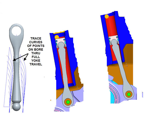
I have an assembly with a mechanism. It contains a link, pinned on both ends, with one pin a rotating arm and the other into a piston in a cylinder with a slider joint. I am trying to maximize the thickness of the link with respect to it's long axis. The limitation is the clearance to the cylinder walls. What I have done is put points on the cylinder and then used the trace curve function to produce trace curves on the link. Then I used those curves as references for the profile of the link all the way around. It looks like this with the link round in cross section with varying diameters as shown:
The issue is that since the link is NOT free to rotate, it COULD be thicker in the direction perpendicular to the ones shown above. Essentially, it could have an oval or elliptical cross section of varying size. The point/trace curve method described above would work, and since there is symmetry I only have to do this for 180º around the link axis as opposed to 360º, but it seems tedious. SOOOOOOO... I am wondering if there is a better way? Maybe something I am missing? Any suggestions???
thanks in advance....
Paul Korenkiewicz
FEV, Inc.
4554 Glenmeade
Auburn Hills, MI., 48326
This thread is inactive and closed by the PTC Community Management Team. If you would like to provide a reply and re-open this thread, please notify the moderator and reference the thread. You may also use "Start a topic" button to ask a new question. Please be sure to include what version of the PTC product you are using so another community member knowledgeable about your version may be able to assist.
4 REPLIES 4
Nov 30, 2010
03:04 AM
- Mark as New
- Bookmark
- Subscribe
- Mute
- Subscribe to RSS Feed
- Permalink
- Notify Moderator
Nov 30, 2010
03:04 AM
A motion envelope would cover the 3D problem compared to the trace curves 2D nature.
If you have access to Behavioral Modeling Extension you could try optimizing it that way using e.g. a minimum clearance value measured between the arm and cylinder. But you will need some good driving dimensions.
Bjarne Frandsen
Nov 30, 2010
06:08 AM
- Mark as New
- Bookmark
- Subscribe
- Mute
- Subscribe to RSS Feed
- Permalink
- Notify Moderator
Nov 30, 2010
06:08 AM
Paul,
As others have suggested. Try using a motion envelope using the casing as the 'pen' part and the yoke as the 'paper' part. Assemble the resulting faceted part with the yoke and you should be able to modify the yoke part so that the size is maximised. If the part see significant compressive load then I would suggest carrying out a buckling analysis as well as a static analysis. Making the shape oval will not change the buckling mode, so it would probably be simpler to keep a circular cross section.
Regards,
Rod
Rod Giles
Polaris Industries
Nov 30, 2010
07:15 AM
- Mark as New
- Bookmark
- Subscribe
- Mute
- Subscribe to RSS Feed
- Permalink
- Notify Moderator
Nov 30, 2010
07:15 AM
That would give me the shape of the motion of the moving link and a
fixed cylinder. Essentially I need the shape of the cylinder with
respect to a fixed link so I can maximize the link.
Thanks...
Paul Korenkiewicz
FEV, Inc.
4554 Glenmeade
Auburn Hills, MI., 48326
fixed cylinder. Essentially I need the shape of the cylinder with
respect to a fixed link so I can maximize the link.
Thanks...
Paul Korenkiewicz
FEV, Inc.
4554 Glenmeade
Auburn Hills, MI., 48326
Dec 01, 2010
07:45 AM
- Mark as New
- Bookmark
- Subscribe
- Mute
- Subscribe to RSS Feed
- Permalink
- Notify Moderator
Dec 01, 2010
07:45 AM
Guru's
This suggestion below seems to indicate that you can set "pen" and "paper" parts for motion envelopes. As far as I can see, there are no options for this. Does anyone know HOW you can do this? What are the picks?
Essentially, if I redefined my mechanism such that the link was the ground/stationary part and the cylinder is the moving part a motion envelope WOULD give me what I need. I'll have to think about how difficult that would be, but it could be pretty slick...
The other good suggestion was to use BMX to run an optimization. Essentially, I could set up the link as a multi-section sweep and run the optimization to tweak the individual section dimensions to a given clearance...
Thanks...
Paul Korenkiewicz
FEV, Inc.
4554 Glenmeade
Auburn Hills, MI., 48326
Announcements
Top Tags
