
Turn on suggestions
Auto-suggest helps you quickly narrow down your search results by suggesting possible matches as you type.
Showing results for
Turn on suggestions
Auto-suggest helps you quickly narrow down your search results by suggesting possible matches as you type.
Showing results for
- Community
- Creo+ and Creo Parametric
- Analysis
- "Midsurface by face pairs"
Options
- Subscribe to RSS Feed
- Mark Topic as New
- Mark Topic as Read
- Float this Topic for Current User
- Bookmark
- Subscribe
- Mute
- Printer Friendly Page
"Midsurface by face pairs"
Oct 28, 2013
09:08 AM
- Mark as New
- Bookmark
- Subscribe
- Mute
- Subscribe to RSS Feed
- Permalink
- Notify Moderator
Oct 28, 2013
09:08 AM
"Midsurface by face pairs"
Hello,
Is there in CREO 2.0 a function similar to "midsurface by face pairs" that can be found in NX? I used to use it a lot for the design of hydraulic turbines blades...
This thread is inactive and closed by the PTC Community Management Team. If you would like to provide a reply and re-open this thread, please notify the moderator and reference the thread. You may also use "Start a topic" button to ask a new question. Please be sure to include what version of the PTC product you are using so another community member knowledgeable about your version may be able to assist.
Solved! Go to Solution.
Labels:
- Labels:
-
General
1 ACCEPTED SOLUTION
Accepted Solutions
Oct 29, 2013
01:00 AM
- Mark as New
- Bookmark
- Subscribe
- Mute
- Subscribe to RSS Feed
- Permalink
- Notify Moderator
Oct 29, 2013
01:00 AM
Sweeps like tangent origins, but it appears that chains can have sharp corners. So it worked exactly as you intended.
I added the part file. This is Creo 2.0 full version if you can use it.
12 REPLIES 12
Oct 28, 2013
07:16 PM
- Mark as New
- Bookmark
- Subscribe
- Mute
- Subscribe to RSS Feed
- Permalink
- Notify Moderator
Oct 28, 2013
07:16 PM
In Creo Parametric, this is done with relations. You have several ways to get there including a saved measurement, or to use a feature's value and performing an operation on it (in this case, divide by 2).
Oct 28, 2013
09:41 PM
- Mark as New
- Bookmark
- Subscribe
- Mute
- Subscribe to RSS Feed
- Permalink
- Notify Moderator
Oct 28, 2013
09:41 PM
Thank you for your answer Antonius, but...do you have an example???
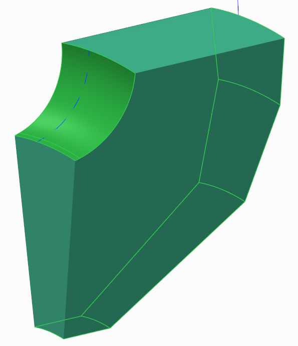
How would you proceed with the two sets of surfaces highlighted?
Oct 28, 2013
11:18 PM
- Mark as New
- Bookmark
- Subscribe
- Mute
- Subscribe to RSS Feed
- Permalink
- Notify Moderator
Oct 28, 2013
11:18 PM
Can you sketch the approximate solution of what you are thinking the result is? I am not certain of the solution you seek here.
Oct 28, 2013
11:38 PM
- Mark as New
- Bookmark
- Subscribe
- Mute
- Subscribe to RSS Feed
- Permalink
- Notify Moderator
Oct 28, 2013
11:38 PM
Ok, from a 2D perspective, I am trying to generate a curve going through the centers of as many circles as possible, without having to draw it manually. Each circle is tangent to both purple curves. 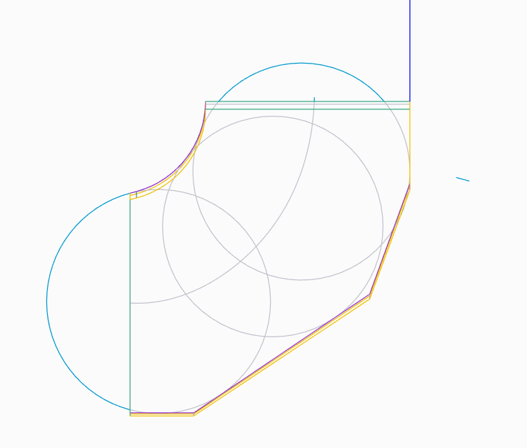
Oct 29, 2013
12:19 AM
- Mark as New
- Bookmark
- Subscribe
- Mute
- Subscribe to RSS Feed
- Permalink
- Notify Moderator
Oct 29, 2013
12:19 AM
Thank you clarifying that. This would be a complicated equation. I am not sure if there is any easy, or even reliable way to create a true "midcurve".
In your sketch you are showing the corners on the lower curves being ignored with your method. This means you can radius, or "round" these curves. Doing that allows you to us a variable section sweep to achieve your "midcurve". Is there an imaginary center point at the intersection of the top horizontal and the left vertical elements? You have to be very careful of how you use the normal of the swept line since it can interpreted in many ways. A constant angular sweep would assure distribution along a sweep would disregard the length of your two guide chains.
I will see what I can come up with, but do you understand how the radii are truncating the resulting midline?
Oct 29, 2013
12:47 AM
- Mark as New
- Bookmark
- Subscribe
- Mute
- Subscribe to RSS Feed
- Permalink
- Notify Moderator
Oct 29, 2013
12:47 AM
First, Thank you for your Help Antonius. As you guessed, the curve starts at the middle point of the vertical/bottom segment, and ends at the middle of the horizontal/top segment. I was trying as much as possible not to temper the bottom curve, and sorry for ignoring the corners, it was not intentional .If adding rounds can help, I think I will make them as small as possible in order to keep the midline as close as possible to its intended shape. They tend to make the midline look smoother than it should, and it could be a problem in the end...
Also, my final goal here is to plot the distance covered by a point on the midcurve(The origin being the vertical/bottom segment ) against the surface of the circle centered on that point and tangent to the purple curves. The obtained curve is then compared with existing data.
I'm intending to do that using a "Field point" with "User-defined Analysis", Or "sensitivity analysis" in Mechanica...
Oct 29, 2013
01:00 AM
- Mark as New
- Bookmark
- Subscribe
- Mute
- Subscribe to RSS Feed
- Permalink
- Notify Moderator
Oct 29, 2013
01:00 AM
Sweeps like tangent origins, but it appears that chains can have sharp corners. So it worked exactly as you intended.
I added the part file. This is Creo 2.0 full version if you can use it.
Oct 29, 2013
12:55 AM
- Mark as New
- Bookmark
- Subscribe
- Mute
- Subscribe to RSS Feed
- Permalink
- Notify Moderator
Oct 29, 2013
12:55 AM
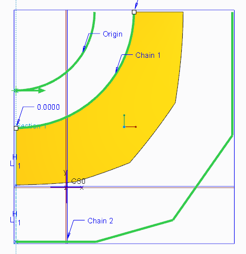
So this is what I came up with if we didn't do circles but determined a true midcurve if we have a theoretical "axis":
This is a Sweep using the Variable Section option.
The origin curve (1/4 arc) is located at the assumed center. Then there are 2 chains (guide curves). The chains are two separate sketches. The Sweep sketch is two equal length lines; one geometry, and one construction. As they sweep along the 1/4 circle, they vary to match equal lengths along the two chains. IN this case, the result is a surface. You can use the edge of the surface in a sketch for further processing.
Oct 29, 2013
12:58 AM
- Mark as New
- Bookmark
- Subscribe
- Mute
- Subscribe to RSS Feed
- Permalink
- Notify Moderator
Oct 29, 2013
12:58 AM
FAST!!!!
Thank you I will try it!!!
Oct 29, 2013
02:30 AM
- Mark as New
- Bookmark
- Subscribe
- Mute
- Subscribe to RSS Feed
- Permalink
- Notify Moderator
Oct 29, 2013
02:30 AM
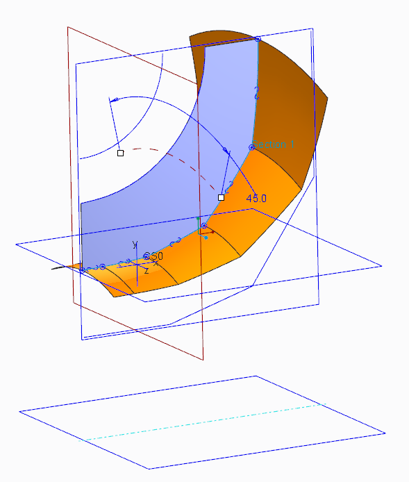
I'm back with another question for you Antonius. what if your origin curve is not a 1/4 arc,but actually bstarts by a straigtht line like below?
does it still Work?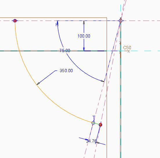
Oct 29, 2013
03:14 AM
- Mark as New
- Bookmark
- Subscribe
- Mute
- Subscribe to RSS Feed
- Permalink
- Notify Moderator
Oct 29, 2013
03:14 AM
I know I'm replying to myself but....It does work...Thank you Antonius
Oct 29, 2013
12:46 PM
- Mark as New
- Bookmark
- Subscribe
- Mute
- Subscribe to RSS Feed
- Permalink
- Notify Moderator
Oct 29, 2013
12:46 PM
You are welcome Stephany.
I did see the line at the end of the arc in your original model. In my model, the "origin" is a full 1/4 arc. The variable sketch will sweep normal to the arc I created in space. By default, the sketches need an orientation throughout the sweep. Often times, the geometry does not offer that normal so we need to create one. Chain 1 and Chain 2 are actually the guiding features of the sketch geometry. In the sketch, I made sure that the distance between the two intersecting points was divided by 2.
The difference in some cases is very subtle when in others is creates crossovers or incomplete sweeps where one or both ends are not the starts or ends. In your example, I choose to use a centerpoint because I was a assuming a toroidal geometry. However, rather than a true arc, I could have used an ellipse or spline as the Origin curve.
There really are a huge number of variations that your result could take on. That is part of what makes Creo so powerful... it rarely assumes -for- you. But this also means we have to think more critically as to what we are trying to achieve.
Announcements
Top Tags
