
Turn on suggestions
Auto-suggest helps you quickly narrow down your search results by suggesting possible matches as you type.
Showing results for
Turn on suggestions
Auto-suggest helps you quickly narrow down your search results by suggesting possible matches as you type.
Showing results for
- Community
- Customer Success
- PTC University Training
- Re: Singularity on edge, trying to remove
Options
- Subscribe to RSS Feed
- Mark Topic as New
- Mark Topic as Read
- Float this Topic for Current User
- Bookmark
- Subscribe
- Mute
- Printer Friendly Page
Singularity on edge, trying to remove
Nov 18, 2015
04:25 PM
- Mark as New
- Bookmark
- Subscribe
- Mute
- Subscribe to RSS Feed
- Permalink
- Notify Moderator
Nov 18, 2015
04:25 PM
Singularity on edge, trying to remove
Hi All,
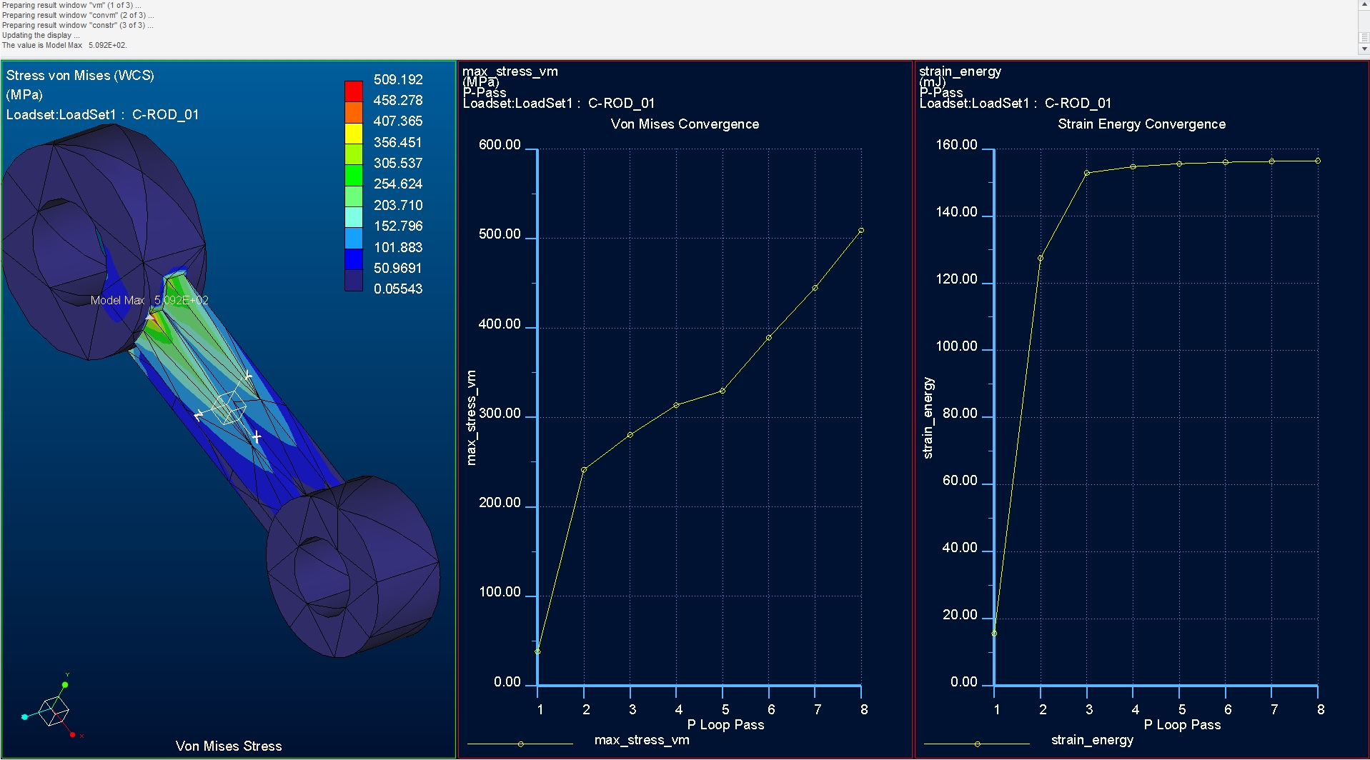
I’m having a bit of a hard time with this. I seem to have a singularity, and I can’t get away from it. I’ve done a few simple models akin to what I’d expect here at work, and each seem to have convergence issues. I’ve tried various methods, but it’s always there. My Von Mises graph is always rising, although some to a lesser degree, always rising.
Today I’m attempting the ‘connecting rod’ model from the ‘Toogood’ book, Creo Simulate Tutorial. Of numerous analyses run, my singularities are always one of the two points highlighted. No matter how I try to isolate these corners/points, I can’t get convergence. I’ve tried multiple attempts at excluded edges & points and re-entrant corners. I’ve even been playing with mesh sizes.. Nothing seems to correct, or lessen the convergence rise. Mind you, I am getting better at knowing what to turn off, what to turn on, and what / how that affects the results.
I’m currently playing with the geometry, and adding rounds to the 90° edges. While that does improve things, I don’t’ feel it’s quite the right thing to do.
I am at a bit of a loss to explain, or rationalize what I’m getting..
Labels:
- Labels:
-
Other
7 REPLIES 7
Nov 19, 2015
02:37 AM
- Mark as New
- Bookmark
- Subscribe
- Mute
- Subscribe to RSS Feed
- Permalink
- Notify Moderator
Nov 19, 2015
02:37 AM
Difficult to say exactly what it is without the model, but keep the following in mind:
-Point/edge loads and constraints on solids produce theoretically infinite stress and models with such entities will not converge
-reentrant corners do not converge
-constraints have infinite stiffness. This can sometimes result in a singularity or unnatural stress concentrations, depending on geometry, even if they are applied to solid surfaces.
-Use rigid/weighted links if you want to create moment free constraints on solids, without creating a singularity (which will be the result if you constrain a point/edge).
-Make use of symmetry if possible. This provides a means to create more natural, realistic constraints, without introducing singularities and/or overconstraining the model.
-In some cases, even with a good model without singularites, it is necessary to refine the mesh at critical locations.This is often the case for models with contacts.
-Creo Simulate is an adaptive software that tries to refine the solution everywhere in the model, including singularities. So attention must be paid to singularities and unnatural stress concentrations that are the result of the modeling technique. In other non-adaptive solvers singularities can be overcome by simply creating a too coarse mesh that cannot capture the high stress gradients that occur near singularities.
Nov 19, 2015
04:15 AM
- Mark as New
- Bookmark
- Subscribe
- Mute
- Subscribe to RSS Feed
- Permalink
- Notify Moderator
Nov 19, 2015
04:15 AM
Paul,
I think you are being misled by system global measures and perhaps some more info on 'isolate for exclusion'. Hope this helps
Ensure that you have excluded elements selected in the analysis definition form (sounds like you have)

Your graph shows 'max_stress_vm' measure is plotted. This is a 'hard wired' measure and it reports the maximum numerical value of vm stress in your model and disregards location. From pass to pass, the numerical solution can also cause the location of the highest numerical value to move about. The global system hard wired measure you have used doesn't care about location.
In your model, the global max of vm stress measure you have used will 99.999% of times be at the sharp corners regardless of whether you have 'excluded' elements or not. The graph of these stresses is not going to be useful. (Other than telling you that there is a very high stress likely at that location and you must rationalise its existence or manage it by design change)
If you want reasonable numerical stresses at these locations then you need reasonable approximations of geometry at these locations. i.e. put a round in, a tool tip radius say. Refine the mesh at this new geometry ...
Excluding elements only removes the elements that touch the edge (or other feature) from the convergence calculation. Your elements are big and cover a lot of structure beyond the offending corner(s)... easier to provide a links to Tad's blog here ...
Singularities and Isolate for Exclusion AutoGEM Controls
"Creo Simulate computes a stress value that is too high and that does not match FEA-program-X"
I would propose the following:
1. You know that the stresses at the sharp corner a high. It is a sharp corner, the stresses will never converge. Rationalise them or adjust the geometry and converge them.
2. Confirm the convergence at more useful locations. Create measures to record the stress/strains at some more useful location and converge on this (these) measures rather than the 'global' and 'system hard wired' measure and converge on these measures instead. Do this from within the analysis definition form (below).
3. Refine your approach to exclusion and don't exclude the elements from the convergence calculation you should include. Don't forget, you can get fancy with volume/surface regions together with various autogem controls to bound offending edges etc.
4. Ask for Local stress errors in the output tab of the analysis definition form (below). (this output is switched off by default and if you don't ask for it you don't get it * ) Plot the raw errors and examine your intended area of study to confirm that these errors are reasonable.


*When will we save the entire solution and recalculate as required?? I know that last century this was because of 2mb hard drives. But things have moved on and other vendors have been doing it for decades.
Nov 19, 2015
03:40 PM
- Mark as New
- Bookmark
- Subscribe
- Mute
- Subscribe to RSS Feed
- Permalink
- Notify Moderator
Nov 19, 2015
03:40 PM
Hi all,
Thanks for the responses, I'm slowly digesting all that's said. I've attached the model. If I recall, I have rounds suppressed in it..
Nov 27, 2015
03:59 PM
- Mark as New
- Bookmark
- Subscribe
- Mute
- Subscribe to RSS Feed
- Permalink
- Notify Moderator
Nov 27, 2015
03:59 PM
Paul,
I ran across this thread by accident and thought I would add my 2 cents worth.
The responses by Steven Dunker, Charles Simpson, and Mats Lindqvist all contain excellent food for thought. I learned a few things from them myself. Thank you.
What you are experiencing with Creo is common to all new users of FEA - that is, discovering that it is not a magical solution that will give you the "right" answer if only you give it the "right" question. Creating a useful (note that I do not say "correct") model is as much an art as it is science. Granted, there are many tools available in the software (excluded elements, measures, regions, mesh controls, . . .) with which you should be skilled, but it is often a matter of judgement and experience to know when the model is complete or accurate enough for your purposes. You gain that experience by struggling with knotty problems like the connecting rod, which on its surface seems like a pretty trivial model but has many dragons lurking under the surface. Imagine the issues with a more realistic and complicated model, like an aircraft landing gear. But enough philosophical meanderings...
I almost never use the built-in measure "max_stress_VM" because its value will always be corrupted by a singularity to the point of irrelevance. It is as meaningless a number as the number of seconds since your last birthday. Trying to get it to converge is like chasing smoke. As has been pointed out, it is also sometimes mesh dependent, and its location can sometimes jump around with each pass or new mesh. Better to instrument your model with measures that avoid the singularity location(s) that are meaningful to the question you want to ask. Then converge the solution on those measures - this is the best way to set up as efficient and effective model as possible. Beware of brute force solutions, like putting rounds on every edge or re-entrant corner, or remeshing with finer and finer meshes, since these are often overkill (and won't catch the smoke anyway!).
A last comment: I once saw an example of a bolted joint where several models were produced by applying loads and constraints in slightly different ways. All models seemed reasonable and convincing, but they of course produced different results. I have also seen the same model produce slightly different results when run through different builds of the same software (not to mention more subtle things like feature type and/or creation order affecting results even though the net geometry is the same, and so on). So, do not expect agreement of solution values down to the n-th significant digit. I also once heard FEA called "an approximation to a simplification of an assumption" about the real problem, or something like that,so the question to ask is not "Is it right?" but rather "What is my confidence level that it is close enough?".
Best of luck with your efforts.
Roger
Nov 28, 2015
05:56 AM
- Mark as New
- Bookmark
- Subscribe
- Mute
- Subscribe to RSS Feed
- Permalink
- Notify Moderator
Nov 28, 2015
05:56 AM
Hello Roger,
Thanks for this comment and this experience feedback.
Kind regards.
Denis.
(avid reader of your books)
Dec 03, 2015
01:24 PM
- Mark as New
- Bookmark
- Subscribe
- Mute
- Subscribe to RSS Feed
- Permalink
- Notify Moderator
Dec 03, 2015
01:24 PM
Hi Roger, thanks for the support! I'm plugging away, and am slowly coming around to this, this method..
Dec 04, 2015
03:08 AM
- Mark as New
- Bookmark
- Subscribe
- Mute
- Subscribe to RSS Feed
- Permalink
- Notify Moderator
Dec 04, 2015
03:08 AM
We have a junior stress engineer who we are trying to educate, and he keeps asking us "what is the right way to model this"? For reasons stated above he never gets a clear answer. To make matters worse, he gets different answers and hints depending on who he asks the question to. So he is now getting a little bit frustrated because he needs to try lots of different ways to model problems, and in the mean time the manager is questioning his slow progress. But little does he know that he is actually learning a lot. (And we are actually also learning from his various attempts). I know I went through a similar phase, and I suspect many of you did too?
The hardest thing of all though, is to convince him to use hand calculations before actually building an FE model. Sometimes a model that is already quite complex can be replaced by some scribbles on the back of a beer coaster. (Example: interference fit of a metal part inside an aluminium part, heating up the assembly, and check if the parts still have interference). I hope his infinite trust in results from a computer is not exemplary for his generation.
