Community Tip - You can subscribe to a forum, label or individual post and receive email notifications when someone posts a new topic or reply. Learn more! X
- Community
- Augmented Reality
- Vuforia Studio
- Re: PVS File Questions...
- Subscribe to RSS Feed
- Mark Topic as New
- Mark Topic as Read
- Float this Topic for Current User
- Bookmark
- Subscribe
- Mute
- Printer Friendly Page
PVS File Questions...
- Mark as New
- Bookmark
- Subscribe
- Mute
- Subscribe to RSS Feed
- Permalink
- Notify Moderator
PVS File Questions...
Hi there!
Just a bit of background... What I am trying to do seems painfully simple, but it is not available in HoloLens: I just want the user to be able to 'grab' and rotate a 3D Model (or model item) so they can inspect it.
Apparently, this is not possible in 3D Eyewear yet, there are only gestures to move and adjust the whole Spatial Target.
That lead me to investigate rotating the model (or model item) myself with Java Script. What I found out is that, while you can rotate a model (or model item) programmatically, you can't just change the rx/ry/rz variables because those values are the GLOBAL WORLD AXES values. What I want to do is rotate the part in place, similar to what you can do at design-time by manipulating the XYZABC triad (see picture).
This, led me to a conversation with PTC regarding the use of the CAD Shell Tool command utility and the creation of a PVS file which shows, allegedly, all information regarding location and orientation of parts.
So, finally, my question: Does anyone know what is the format if the PVS file? Does anyone have any specification? I can see my individual boolean solids in there, and I do have a 'bbox' value, which I am assuming provides some initial positional reference, but it gets confusing when you look at some of the instantiated children components.
Also, is there a way to find where the*.ol files referenced in the document got exrtacted? I cannot find them.
I guess, ANY information helping me find the location in space of ALL models (or model items) would be appreciated.
Thank you very much!
- Labels:
-
Coding
- Mark as New
- Bookmark
- Subscribe
- Mute
- Subscribe to RSS Feed
- Permalink
- Notify Moderator
Hi @HectorAtLmco ,
I am not sure what is the goal, and how much work you want to invest to implement it.
So, what I believe here- you want to implement:
- some coordinate transformation to have a movement an rotation using any coordinate system in space.
- some input via gestures to have input coordinates for the component movements
For the first point we can check the pvs . In the pvz file (pvz is acctually a zip file) we have .ol file which contains the model geometry and one or more pvs files for implementing of the assembly structure ( mostly one pvs for each pvz file)
As Info about the pvs here is an overview of Creo View Data Structures (part of the Creo View toolkit documentation)
//===========================================
At the top level, the Creo View kernel contains a World. This is created and
populated when you load a .pvs or .ed file. A world contains a Structure.
This structure represents the hierarchy of parts (also known as components) in that
world. For example, consider a structure made up of 3 parts:
• Trolley
• Axle
• Wheel
These can be pulled into an assembly referred to as a Tree, and which represents
the real trolley with 2 axles and 4 wheels.
However, the 2 axles are identical to each other as are the wheels except for their
locations. As each wheel may have a lot of shared information, we ensure that this
information is stored in memory and build this assembly up from components.
The component acts as a storage vessel in a file structure. It is used to hold
properties which store or reference the actual data or other subcomponents.
Components are of several types:
• ComponentNode—Data items that contain all the shared information. These
need to be referenced by a ComponentInstance before they are created in the tree. To create children of these nodes the ComponentProxy or
ComponentInstances should be added as children.
• ComponentProxy—Used to reference children that are contained in a
seperate .pvs file.
• ComponentInstance—References a ComponentNode or
ComponentProxy and creates an instance of that ComponentNode in the
Tree. Properties of the ComponentNode, such as location or color, can be
overridden in a ComponentInstance.
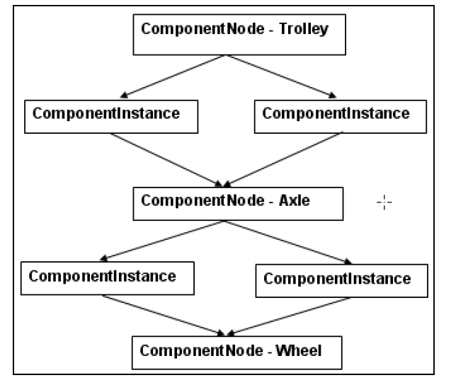
A ComponentInstance creates an instance of a ComponentNode or
ComponentProxy when it is instantiated in the Tree. Therefore, the assembly
above can be represented as follows:
Each ComponentNode contains the same information for all instances of that
component, that is, the properties and files names of secondary content such as 3D
shapes, drawings, images, and so on. This hierarchy is grouped under a structure.
A structure can be associated with a .pvs file and represents the contents of that
file.
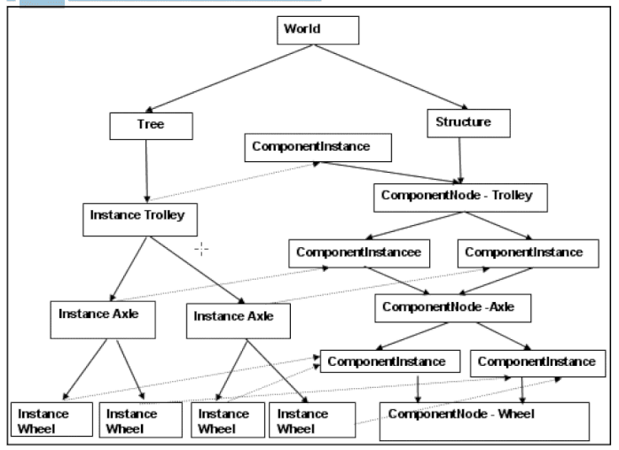
To realize the fully expanded instance structure, the structure is expanded to create
a Tree that contains instances as follows:
Methods are provided on the instance to access information. However, these
methods retrieve the relevant information from the ComponentInstance or
ComponentNode. The information is therefore, stored only where necessary.
However, information may be overridden at each level, for example, each wheel
could be given a different name or have a unique property. Information which is
only relevant at the Instance level such as the 3D position of the instance is stored
at that level.
When you want to look at some data in the World in the view window, you must
first create a scene. Different types of scenes are as follows:
• ShapeScene—A shape scene has a list of parts that are loaded and visible in
it. It also has a selection list.
• DrawingScene—A drawing scene
• ImageScene—An image scene
• DocumentScene—A document scene
Having created a scene, you cannot see it. To be able to see any data you need a
View. A view adds view point information to the scene, for example, the
orientation for the parts in a scene. One scene can have multiple views. As views share the scene, if you unload a part in the scene, all the views would see that part
disappear.
=====================================
1.) what Info we can read from the pvs file
1.1.)we can read the coordinates for each component in euler angle notation x,y,z, rx,ry,rz, (xyz translation and rx,ry,rz rotations) For this we can use creo view toolkit (java , web or Web.gl toolkit - tools provided by PTC) This requires some programming work. IT is possible that already implementation of such tools based on Creo View toolkit exist already and are offered by some ptc dev partners
1.2) we can also extract the components via the ui. When we check an assembly in Creo View (express)
We can do the same in Vuforia Studio when we define for each compoent a modelItem widget and specify the correct Component Occurrence /in studio Component /Part Id path - in Creo View
So we can see that when we define a modelItem for each component /path we can extract manually with some additional work the coordinates for specific component branch.
ROOT CSYS - SubAssembly CSYS .... Part CSYS (part default coordinate system)
This means all points in an geometry files are in respect to the part coordinate system. This could be different depending how the part was created. For example you can have a cube where the coord system origin is in the top left front corner or on the bottom , right corner or in the middle of the cube etc.… For the PVZ file this definition is implemented in the *.ol / geometries files
Then in the assembly pvs file we have assemblies and subassemblies definitions. For example in a assembly we ca define for each component the x,y,z, rx,ry,rz of the part csys. When we have a sub assembly then we have to use the sub assembly coordinate system. This means that the coordinate what we achieve for a component is always in respect to the parent assembly. When we have more levels of components, we have to calculated the coordinates along the assembly component paths.
Here we have to pay attention that the coordinate information what we will achieve form the pvs file via Toolkit or via UI depends of the structure of the assembly ,what of coordinate system are used and also how to components are assembled ( by csys , by aligning of some surfaces etc...)
Another question is - what we could do with this coordinate informations?
It is possible that you can use any csys and achive specific rotation and tranformation (via any axis ). In this case you need to calculate the correct transofrmation matrix in respect to the existing assembly coordinate systems
- Mark as New
- Bookmark
- Subscribe
- Mute
- Subscribe to RSS Feed
- Permalink
- Notify Moderator
in the article How can we make a 3D Widget on HoloLens visible in front of me everytime ?
there is an example project for dynamic widgets on HoloLens. There I provided a libraries which calculate the 3d transformation in space and read the eye position and the eye direction vector. Maybe it could be helpful in your case
- Mark as New
- Bookmark
- Subscribe
- Mute
- Subscribe to RSS Feed
- Permalink
- Notify Moderator
Hi Roland!
I am so sorry for the delay in this reply. I've been a tad busy with other duties. While I still haven't solved the problem, your insightful explanation about the relationship in the parts as well as 'inheritance' of attributes I think will be fundamental to find a solution. I am hoping to do some more tinkering this Holiday break and will report back.
In the mean time, THANK YOU so much for the very complete information!
- Mark as New
- Bookmark
- Subscribe
- Mute
- Subscribe to RSS Feed
- Permalink
- Notify Moderator
what is the actual usecase / requirement for knowing the location of the model/modelitems?
you know the location of the modelitem - it is given to you when you create it. Is this information not sufficient for your task?
- Mark as New
- Bookmark
- Subscribe
- Mute
- Subscribe to RSS Feed
- Permalink
- Notify Moderator
Hi.
Unfortunately no. That was the first thing I tried, just changing rx incrementally to make it seem like the part is rotating. This is what led my discovery that what you rotate is the Global 0,0,0 and not the part's Geometric Center.
I confess I haven't had time to evaluate the very complete answer posted above, I've been tied up with other things. I am hoping I'll be able to tinker this Holiday break.


