
Turn on suggestions
Auto-suggest helps you quickly narrow down your search results by suggesting possible matches as you type.
Showing results for
Turn on suggestions
Auto-suggest helps you quickly narrow down your search results by suggesting possible matches as you type.
Showing results for
Community Tip - Stay updated on what is happening on the PTC Community by subscribing to PTC Community Announcements. X
- Community
- Creo+ and Creo Parametric
- 3D Part & Assembly Design
- Re: Inquiry Regarding Flat Pattern Generation and ...
Options
- Subscribe to RSS Feed
- Mark Topic as New
- Mark Topic as Read
- Float this Topic for Current User
- Bookmark
- Subscribe
- Mute
- Printer Friendly Page
Inquiry Regarding Flat Pattern Generation and Feature Suppression in Image ?
Sep 29, 2023
04:29 PM
- Mark as New
- Bookmark
- Subscribe
- Mute
- Subscribe to RSS Feed
- Permalink
- Notify Moderator
Sep 29, 2023
04:29 PM
Inquiry Regarding Flat Pattern Generation and Feature Suppression in Image ?
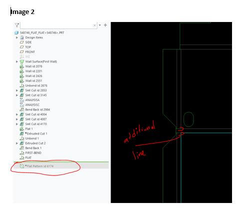
Could someone please clarify why an additional line is appearing on the V-notch in Image 2? Additionally, what distinguishes the process of generating a flat pattern directly from the "customize graphics toolbar" compared to using the unbend features from the "Ribbon" and then creating the flat pattern from the family table after suppressing all features?
In Image-1, I generated the flat pattern using the customize graphics toolbar.
In Image-2, I utilized the bend feature from the toolbar and suppressed all features in the family table after all bends were made.
Image-1
Image-2
Solved! Go to Solution.
Labels:
- Labels:
-
2D Drawing
-
3D Animation
-
Sheet Metal Design
1 ACCEPTED SOLUTION
Accepted Solutions
Oct 02, 2023
12:24 PM
- Mark as New
- Bookmark
- Subscribe
- Mute
- Subscribe to RSS Feed
- Permalink
- Notify Moderator
Oct 02, 2023
12:24 PM
The unbend operation will allow you to unbend any or all bends in order to perform other operations such as create your own relief cuts then bend it back to continue. The flat pattern feature always stays at the end of the model tree and flattens all bends and forms.
By suppressing the bend features, to get back to your original shape, the bent areas no longer exist in the model.
To remove the tangent lines in the drawing, use Edge Display to erase those lines.
There is always more to learn in Creo.
8 REPLIES 8
Oct 02, 2023
08:04 AM
- Mark as New
- Bookmark
- Subscribe
- Mute
- Subscribe to RSS Feed
- Permalink
- Notify Moderator
Oct 02, 2023
08:04 AM
I'll have to say I can't see anything. The image quality it really bad and I can't see any difference.
Oct 02, 2023
10:44 AM
- Mark as New
- Bookmark
- Subscribe
- Mute
- Subscribe to RSS Feed
- Permalink
- Notify Moderator
Oct 02, 2023
10:44 AM


Oct 02, 2023
10:58 AM
- Mark as New
- Bookmark
- Subscribe
- Mute
- Subscribe to RSS Feed
- Permalink
- Notify Moderator
Oct 02, 2023
10:58 AM
Those are tangent lines for the bend. I'm assuming that's the bend centerline in the view.
The 2 ways to create the flat today are family table (Pro/e flat state) and the simplified rep flat which was introduced at some point, not sure when.
Oct 02, 2023
11:20 AM
- Mark as New
- Bookmark
- Subscribe
- Mute
- Subscribe to RSS Feed
- Permalink
- Notify Moderator
Oct 02, 2023
11:20 AM
Are you modeling the flat shape then bending it, with image 1 being the original shape and image 2 being a generated flat pattern? If this is the case, the added lines are tangent lines, as @StephenW pointed out., that define the bend area, created in the bend operation.
There is always more to learn in Creo.
Oct 02, 2023
11:43 AM
- Mark as New
- Bookmark
- Subscribe
- Mute
- Subscribe to RSS Feed
- Permalink
- Notify Moderator
Oct 02, 2023
11:43 AM
Thank you for the reply and looking on this .
Yes, I model the 3D sheet metal shape and bending it to create a flat pattern.
I see that tangent line when I create the flat pattern as DXF for programming for the bending one. Which I do not want to display in the programming? As I discovered later, the flat pattern generated from Flat pattern does not have that tangent line in the dxf. Just wondering why the same flat pattern comes in different forms?
Oct 02, 2023
12:24 PM
- Mark as New
- Bookmark
- Subscribe
- Mute
- Subscribe to RSS Feed
- Permalink
- Notify Moderator
Oct 02, 2023
12:24 PM
The unbend operation will allow you to unbend any or all bends in order to perform other operations such as create your own relief cuts then bend it back to continue. The flat pattern feature always stays at the end of the model tree and flattens all bends and forms.
By suppressing the bend features, to get back to your original shape, the bent areas no longer exist in the model.
To remove the tangent lines in the drawing, use Edge Display to erase those lines.
There is always more to learn in Creo.
Oct 02, 2023
04:20 PM
- Mark as New
- Bookmark
- Subscribe
- Mute
- Subscribe to RSS Feed
- Permalink
- Notify Moderator
Oct 02, 2023
10:46 AM
- Mark as New
- Bookmark
- Subscribe
- Mute
- Subscribe to RSS Feed
- Permalink
- Notify Moderator
Oct 02, 2023
10:46 AM
I have just updated the two images with better quality. I appreciate you taking the time to look at this.
