
Turn on suggestions
Auto-suggest helps you quickly narrow down your search results by suggesting possible matches as you type.
Showing results for
Turn on suggestions
Auto-suggest helps you quickly narrow down your search results by suggesting possible matches as you type.
Showing results for
- Community
- Creo+ and Creo Parametric
- Analysis
- How to Idealize Guy wires working under tension on...
Options
- Subscribe to RSS Feed
- Mark Topic as New
- Mark Topic as Read
- Float this Topic for Current User
- Bookmark
- Subscribe
- Mute
- Printer Friendly Page
How to Idealize Guy wires working under tension only that support silencer chimneys
Jan 02, 2024
07:43 AM
- Mark as New
- Bookmark
- Subscribe
- Mute
- Subscribe to RSS Feed
- Permalink
- Notify Moderator
Jan 02, 2024
07:43 AM
How to Idealize Guy wires working under tension only that support silencer chimneys
Hello PTC community,
I am using Creo Simulate (version 7) to perform the following FEA study. I need to idealize four Guy wires within the genset exhaust and silencer assembly that will help stabilize the chimney when high wind loads might be experienced. The four Guy wires are meant to be attached to the frame which is supposed to be mounted onto the flange of the top most part of the chimney as shown in the pictures attached.
I have tried single and multiple beam elements till now but both of them behave unnaturally. I have used a rigid connection at the top for connecting frame and the beam elements and have used fixed translation free rotation for all at the bottom point (ground) of the beam. Please see attached some of the pictures that will help communicate better.
For the single beam element, when wind loading is experienced, two ropes must be in tension like state while the opposite two must behave different to these. However, all four more or less seem to behave the same? Also the behavior of these ropes at a scaling factor 1 (actual deformation) does not seem to be natural as the ropes could be seen sagging towards the ground. Would that be because of the own weight of the ropes? Because the solver has been specified with own load of the assembly to be taken into consideration as well along with the wind loads.
Please guide.
Solved! Go to Solution.
Labels:
- Labels:
-
Simulate
1 ACCEPTED SOLUTION
Accepted Solutions
Jan 02, 2024
11:55 AM
- Mark as New
- Bookmark
- Subscribe
- Mute
- Subscribe to RSS Feed
- Permalink
- Notify Moderator
Jan 02, 2024
11:55 AM
The step @YT_4948 is missing is using prestress analysis. The standard linear analysis uses superposition so the sag of the guys due to gravity does not account for pretension - it is done independently. I have attached a complete example for a tower with guy wires modelled as beam elements that includes the incorrect and the correct prestress techniques for the static and the modal cases. Also an example for the buckling case is included but you would need to suppress the beams for that example. This is Creo 10 so hopefully you can upgrade to see it.
FYI this is a similar technique as that used for stringed musical instruments.

Wind and Gravity + Pretension = WRONG ANSWER

Run pretension first, and then Prestress static and you get correct results.

First/LH case below has the check box to include the results from the pretension run.

The increase and decrease in tension in the wires due to the wind load are also correct and there is no exaggerated sag due to gravity.

I believe if solid elements were used, a non-linear analysis would provide correct final results without the need for a pretension analysis step. Also, with non-linear analysis you can time-stagger the loads, accomplishing the pretension in another way.
- Tags:
- howto
12 REPLIES 12
Jan 02, 2024
07:49 AM
- Mark as New
- Bookmark
- Subscribe
- Mute
- Subscribe to RSS Feed
- Permalink
- Notify Moderator
Jan 02, 2024
07:49 AM
Beam elements are not the solution as you have found. Take a look at this old thread dealing with the same issue.
How to simulate and analyze a steel rope (steel ca... - PTC Community
========================================
Involute Development, LLC
Consulting Engineers
Specialists in Creo Parametric
Involute Development, LLC
Consulting Engineers
Specialists in Creo Parametric
Jan 02, 2024
07:55 AM
- Mark as New
- Bookmark
- Subscribe
- Mute
- Subscribe to RSS Feed
- Permalink
- Notify Moderator
Jan 02, 2024
07:55 AM
Thanks a lot. It looks interesting.
Jan 02, 2024
11:20 AM
- Mark as New
- Bookmark
- Subscribe
- Mute
- Subscribe to RSS Feed
- Permalink
- Notify Moderator
Jan 02, 2024
11:20 AM
I have went through the above mentioned thread and have now got spring elements (point-point) in my model. I have also used the same if/else function however I only specified range from 0 to 10 as I only expect the guy wires to work only in tension in real life. The constraints are now as follows:
1) Rigid connection between springs and top frame.
2) Fixed translation for Y and Z. Free translation for X (along the axis of the rope) just to make sure the force (200N - just an assumption) that I have specified downwards along the axis there is taken into consideration. All rotations free at the bottom of the ropes.
Now, when I try to run a non linear analysis checking the NON-LINEAR tick box, the solver gives an error (Screenshot attached below). Is it because of the rigid connection I have specified? If, yes what different constraints shall I use? Please guide if I am correctly approaching this.
Please note that I am still trying to use CREO Simulate and NOT Mechanica for this analysis.
Jan 02, 2024
12:03 PM
- Mark as New
- Bookmark
- Subscribe
- Mute
- Subscribe to RSS Feed
- Permalink
- Notify Moderator
Jan 02, 2024
12:03 PM
You cannot use shells and beams in non-linear analysis. The geometry would need to be solid and the guys probably can be as springs, but would still need pre-tensioning. Creo Simulate is Mechanica, they just changed the name.
Jan 02, 2024
11:55 AM
- Mark as New
- Bookmark
- Subscribe
- Mute
- Subscribe to RSS Feed
- Permalink
- Notify Moderator
Jan 02, 2024
11:55 AM
The step @YT_4948 is missing is using prestress analysis. The standard linear analysis uses superposition so the sag of the guys due to gravity does not account for pretension - it is done independently. I have attached a complete example for a tower with guy wires modelled as beam elements that includes the incorrect and the correct prestress techniques for the static and the modal cases. Also an example for the buckling case is included but you would need to suppress the beams for that example. This is Creo 10 so hopefully you can upgrade to see it.
FYI this is a similar technique as that used for stringed musical instruments.
Wind and Gravity + Pretension = WRONG ANSWER
Run pretension first, and then Prestress static and you get correct results.
First/LH case below has the check box to include the results from the pretension run.
The increase and decrease in tension in the wires due to the wind load are also correct and there is no exaggerated sag due to gravity.
I believe if solid elements were used, a non-linear analysis would provide correct final results without the need for a pretension analysis step. Also, with non-linear analysis you can time-stagger the loads, accomplishing the pretension in another way.
- Tags:
- howto
Jan 03, 2024
04:24 AM
- Mark as New
- Bookmark
- Subscribe
- Mute
- Subscribe to RSS Feed
- Permalink
- Notify Moderator
Jan 03, 2024
04:24 AM
Thanks a lot for this indepth explanation. I will try it now and hopefully get the correct results this time. Much appreciated 🙂
Jan 03, 2024
06:12 AM
- Mark as New
- Bookmark
- Subscribe
- Mute
- Subscribe to RSS Feed
- Permalink
- Notify Moderator
Jan 03, 2024
06:12 AM
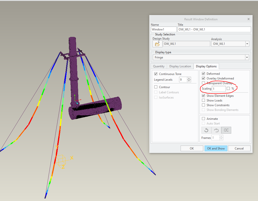
I am a little confused if I must tick this red circled box or not in the attached snip. I could see we have ticked "combine results with results from previous static analysis" though. Should that help as it is or do we still tick the top box circled in red and then proceed? Please guide.
Jan 03, 2024
12:47 PM
- Mark as New
- Bookmark
- Subscribe
- Mute
- Subscribe to RSS Feed
- Permalink
- Notify Moderator
Jan 03, 2024
12:47 PM
Good question, as the circled box can be confusing.
Unchecked - The prestress study is run first as part of the prestress-static and both result are available under the same single study folder structure.
Checked- Means you have already run the prestress study and have a result folder so you are asking to not rerun that study but to continue onward with the 2nd part of the prestress-static study. This does a check to make sure the model is the same and will not run successfully if it detects changes. I find on occasion Creo detects a change when there was not any change. (probably related to geometry problems / approximations)
I prefer unchecked because if I change the model I need to rerun both studies anyway. It is more for saving that analysis time for rerunning the prestress study that the checked option is there. However, if you have multiple Prestress-Static scenarios that all use the same input prestress study by checking the box they could all refer to a single prestress run rather than each running them as part of their own study.
For running multiple studies as part of single study this is the option._1
This would be for a larger sequence of studies that you want to collect together for example based on a specific design variant. (Run modal, several static, buckling, etc as one study called "MyDesign1")

when results are pulled for the study, there will be multiple analysis to pick results from.

Jan 04, 2024
03:13 AM
- Mark as New
- Bookmark
- Subscribe
- Mute
- Subscribe to RSS Feed
- Permalink
- Notify Moderator
Jan 04, 2024
03:13 AM
That is a great explanation @SweetPeasHub. However, what if I only want to see what the prestress (tension in guys) do to the model without the introduction of own weight and wind loading? Running them separately allows me to view results for each (prestress as well as prestress + own weight + wind loading) with two different analyses. Is there any way in the prestress static study that we could only see what the prestress is doing to the model by maybe toggling off the effects of own weight and wind loads? I could however see Prestress analysis has started first and then the prestress static will follow. So does that mean when it is all complete, the results for prestress will still sit under prestress analysis that is defined separately? Please guide 🙂
Jan 08, 2024
07:56 AM
- Mark as New
- Bookmark
- Subscribe
- Mute
- Subscribe to RSS Feed
- Permalink
- Notify Moderator
Jan 08, 2024
07:56 AM
Hello @SweetPeasHub , I have been trying the above mentioned way of simulating the real life scenario where I run the prestress studies first and then prestress static including the own weight as well as the wind loading and it seems to be running much better now. However, I have still got a doubt about the constraints - According to the real life scenario, we will have an anchor fixed to the ground and a shackle fixed up at the frame to which both the points of the Guy wire will be connected to. So, aren't they supposed to have pinned constraints at both the ends while performing the FEA? If so, how do we simulate the prestress at the bottom now if there is a pin constraint there? Please see attached pictures for your reference and kindly guide.
Jan 09, 2024
02:06 AM
- Mark as New
- Bookmark
- Subscribe
- Mute
- Subscribe to RSS Feed
- Permalink
- Notify Moderator
Jan 15, 2024
10:32 AM
- Mark as New
- Bookmark
- Subscribe
- Mute
- Subscribe to RSS Feed
- Permalink
- Notify Moderator
Announcements
Top Tags
