
Turn on suggestions
Auto-suggest helps you quickly narrow down your search results by suggesting possible matches as you type.
Showing results for
Turn on suggestions
Auto-suggest helps you quickly narrow down your search results by suggesting possible matches as you type.
Showing results for
- Community
- Creo+ and Creo Parametric
- Analysis
- Meshing and weld issues for a rain cowl assembly
Options
- Subscribe to RSS Feed
- Mark Topic as New
- Mark Topic as Read
- Float this Topic for Current User
- Bookmark
- Subscribe
- Mute
- Printer Friendly Page
Meshing and weld issues for a rain cowl assembly
Feb 02, 2024
07:37 AM
- Mark as New
- Bookmark
- Subscribe
- Mute
- Subscribe to RSS Feed
- Permalink
- Notify Moderator
Feb 02, 2024
07:37 AM
Meshing and weld issues for a rain cowl assembly
Dear PTC Community,
I am currently working on Creo Simulate to perform a FEA on a rain cowl assembly for different wind loadings and also to check if the current weight of this rain cowl assembly can be taken by the motorised louvers without failing (rain cowl assembly is mounted onto the motorised louvers with the help of bolts).
I have defined fasterners and weld connections wherever needed but facing some issues with them as listed below:
Issue_1: The perimeter welds defined at locations where the top part of the rain cowl assembly is being connected to the side part for example is not being taken into consideration and the solver says that it is taken as bonded idk why?
Issue_2: The end welds along the curve for the same two parts of the rain cowl assembly are ignored by the solver idk why either. (It is treated as bonded there)
Issue_3: Single element at the top left part of the rain cowl assembly shows an error (Can be seen when tried to run the own_weight static design study)
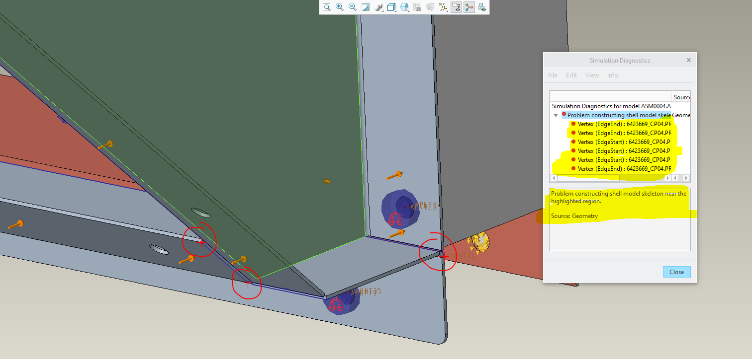
Issue_4: Problems creating shell model skeleton at and near the vertices shown in the attached snips. This is due to the welds defined there it seems as when I suppress the weld connection at those instances, the error vanishes. (NOTE: The mesh is created without the welds but with the welds defined at those instances, the error arises)
One last doubt - In order to check if motorised louvers can take the weight of the rain cowl, we only carry out the analysis for just the own weight (gravity load) without any wind loads right?
Please see attached zip file and snips for your reference. Please guide. Many thanks.
Solved! Go to Solution.
Labels:
- Labels:
-
Simulate
1 ACCEPTED SOLUTION
Accepted Solutions
Feb 07, 2024
02:36 PM
- Mark as New
- Bookmark
- Subscribe
- Mute
- Subscribe to RSS Feed
- Permalink
- Notify Moderator
Feb 07, 2024
02:36 PM
Here is how to annotate the fastener measures.
I would setup the simulation unit system to mm-N-s rather than mm-kg-s

10 REPLIES 10
Feb 06, 2024
07:38 AM
- Mark as New
- Bookmark
- Subscribe
- Mute
- Subscribe to RSS Feed
- Permalink
- Notify Moderator
Feb 06, 2024
07:38 AM
Attached below is a hidden line view that shows the top and side part of the rain cowl assembly currently meeting at a single edge (highlighted in yellow). A fillet weld of 2mm is naturally meant to be in place to connect them in real life. Is the reason behind this weld not being taken into consideration is because there is not enough contact area available there? Just a doubt.

Feb 06, 2024
10:16 AM
- Mark as New
- Bookmark
- Subscribe
- Mute
- Subscribe to RSS Feed
- Permalink
- Notify Moderator
Feb 06, 2024
10:16 AM
I don't think such models work well ☹️
I always build new models especially for Creo Simulate, my example is included.
Feb 06, 2024
10:36 AM
- Mark as New
- Bookmark
- Subscribe
- Mute
- Subscribe to RSS Feed
- Permalink
- Notify Moderator
Feb 06, 2024
10:36 AM
@skunks Ok noted, so you mean we model the welds in the part itself. Also, in order to check if motorised louvers can take the weight of the rain cowl, we only carry out the analysis for just the own weight (gravity load) without any wind loads right? If in this case, the solver still warns that the yield limit has been exceeded for any of these parts, does that mean the weight of the rain cowl assembly can not be taken by the motorised louver?
However, a maximum of 216 MPa can be seen for the own weight run without any wind loads. Theoretically, we are expected to keep it below 235 MPa (Yield Stress) for the actual material used. The material defined to the model for the solver is just a standard material from the working directory. So, looking at the numbers, should the yield warning be ignored and the design should be considered safe? Please guide.


Feb 07, 2024
01:08 AM
- Mark as New
- Bookmark
- Subscribe
- Mute
- Subscribe to RSS Feed
- Permalink
- Notify Moderator
Feb 07, 2024
05:14 AM
- Mark as New
- Bookmark
- Subscribe
- Mute
- Subscribe to RSS Feed
- Permalink
- Notify Moderator
Feb 07, 2024
05:14 AM
Thanks for attaching the test model here @skunks as it really helped me. However, why is the direction for the gravity load in the orientation shown below? Should not it be pointing in the downward direction naturally if it is trying to simulate the own weight of the assembly? Please explain.

Also, now I have got the welds modelled in the assembly and defined the interfaces as well. However, I am facing an issue with one particular surface in terms of meshing. Following is the error snip saying "Problems were encountered while preprocessing the features for the highlighted surface. Source: AutoGem". Any solution to this please?

Feb 07, 2024
05:36 AM
- Mark as New
- Bookmark
- Subscribe
- Mute
- Subscribe to RSS Feed
- Permalink
- Notify Moderator
Feb 07, 2024
05:36 AM
Gravity should of course be pointing downwards,
I wasn't paying attention 😅
I would prefer the shell model, like my example.
The AutoGEM can't cope with the solid geometry, it looks like.
Feb 07, 2024
02:36 PM
- Mark as New
- Bookmark
- Subscribe
- Mute
- Subscribe to RSS Feed
- Permalink
- Notify Moderator
Feb 07, 2024
02:36 PM
Here is how to annotate the fastener measures.
I would setup the simulation unit system to mm-N-s rather than mm-kg-s
Feb 08, 2024
09:52 AM
- Mark as New
- Bookmark
- Subscribe
- Mute
- Subscribe to RSS Feed
- Permalink
- Notify Moderator
Feb 08, 2024
09:52 AM
Thanks a lot for the shell model @skunks and the in depth video explanation @SweetPeasHub as I have been learning a lot honestly. I have a quick doubt here that as we saw in the video that the solver raised the yield warning for the respective material for the gravity load, so does that mean that the louvers are not able to take the weight of the rain cowl assembly? Or is that because of all the fasteners were not defined to hold that weight in place? What if the solver raised the same warning when all the fasteners are in place? Could we still ignore the warnings and conclude based on the actual stress numbers we come across by any means as those warnings might be issued due to some stress singularities maybe? Please guide.
Feb 15, 2024
05:30 PM
- Mark as New
- Bookmark
- Subscribe
- Mute
- Subscribe to RSS Feed
- Permalink
- Notify Moderator
Feb 15, 2024
05:30 PM
Interpretation of stress results and warnings about yielding need careful consideration and experience. There are times when singularities, discontinuities, or other situations cause the warning and yet the analyst does not deem the result a failure. Don't ignore it, rather assume you need to be able to justify the decision.
Feb 16, 2024
04:08 AM
- Mark as New
- Bookmark
- Subscribe
- Mute
- Subscribe to RSS Feed
- Permalink
- Notify Moderator
Announcements
Top Tags
