10-Marble
April 17, 2013
Question

How to change STL faceting of flat circular surfaces

  • April 17, 2013
  • 6 replies
  • 14763 views

Hello everyone, (First Post Ever Alert)

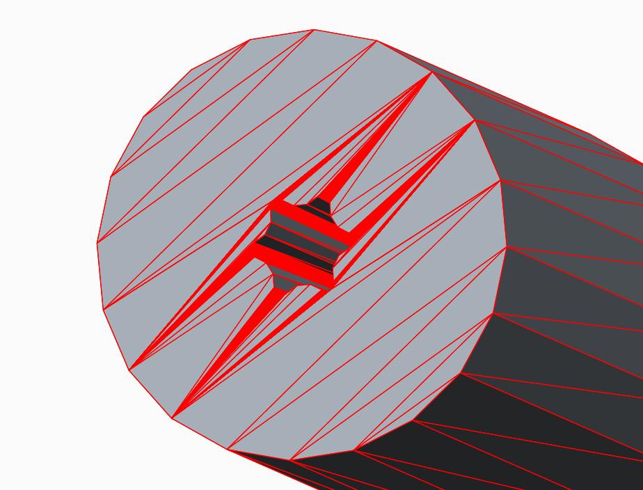
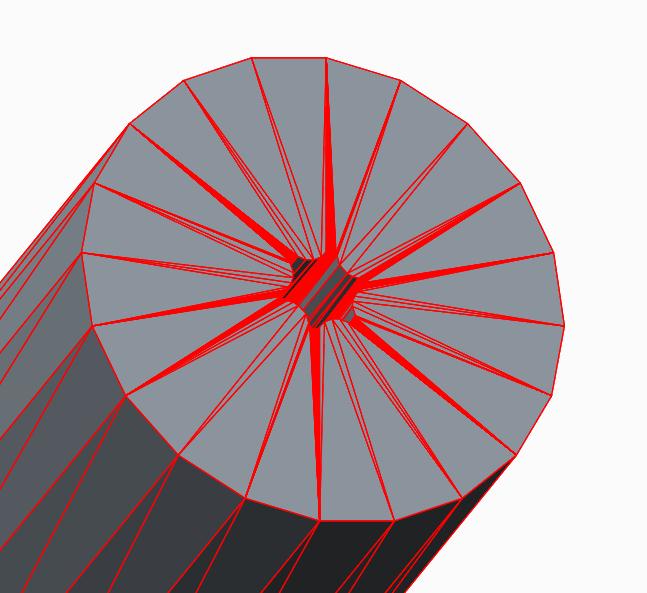
I make a lot of STLs for rapid prototyping and for fea, I want the stl triangles to be arrayed around the center of circular flat surfaces, the way they are when created in DEFORM (http://www.deform.com/).

The only way I have now, is to make all the surfaces either slightly concave or convex. Which works, but sometimes causes issues with the models.

stl_flat.jpgstl_concave.jpg

Thanks for any suggestions!

    6 replies

    Dale_Rosema
    23-Emerald III
    23-Emerald III
    April 17, 2013

    From my many year of rapid prototyping, the triangular pattern on circles have typically been like your picture on the left irregardless of software. I am not sure how the algorithm is written for developing the triangles. If you change your resolution sometimes it will modify how the triangle are made.

    dblaess10-MarbleAuthor
    10-Marble
    April 17, 2013

    Back to Dale,

    It's nice to know it's not just me.

    The only reason I really care, is that in the fea program DEFORM, the mesh is created from these stls and the pattern on the end faces make the mesh behave poorly; which is the reason I do the models with concave/vex surfaces.

    The DEFORM software makes stl models like the picture on the right, but I think everything is considered a simple revolve, so that is most likely the reason.

    Thanks for your response.

    17-Peridot
    April 17, 2013

    See how the VRML export does the faceting. If it is more to your liking, you can then import it again and the STL should now follow the VRML facets fairly closely.

    I have a feeling that the "layering" of the facets in STL is probably intentional as the STL process is cone by layers rather than logical facet divisions. If the above test fails, it is very likely that this is the case and should be considered an enhancement to a generic STL generation.

    Have you looked to see if there are options in the STL export?

    dblaess10-MarbleAuthor
    10-Marble
    April 18, 2013

    Back to Antonius,

    I do like the VRML export better, but after importing and exporting as stl, the results are about the same.

    I may have to live without having flat endfaces on my cylinders.

    I have looked for STL options, but I haven't found any more than are in the export window. I may do more searching.

    My next step is to send it to support and see if they can help (or maybe add it as an enhancement, sometime).

    Patriot_1776
    22-Sapphire II
    April 19, 2013

    Here's the thing, if it's a flat surface, the triangulation is completely irrelevant. Really. ONLY if there is some curve to a surface will it matter. In your case with a flat surface and the splined hole, only the amount of triangulation where the spline intersects the surface matters, not the look. The flat surface will ALWAYS be flat, it's just how accurate does the curve on the spline need to be, because the amount of segments where it intersects the flat plane is what determines the accurace longitudinally down the splined hole.

    I would NEVER make what should be a flat surface concave or convex simply to make the file look better. The system knows what it's doing, don't worry about it. I've never had an issue and I worked at a place with 2 SLA machines I used constantly for about 2 years.

    I haven't created an STL in creo yet, but there should be (read: WAS) settings you could set for, if I remember, chord angle and chord height. They or similar should still exist, just look for them when you create the STL file.

    Best of luck.

    17-Peridot
    April 19, 2013

    Its probably still the same Frank...

    stl_dialog.JPG

    15-Moonstone
    April 22, 2013

    Hi Donald,

    This is an interesting thread to me because we use the DEFORM software. I've used DEFORM for a long time but have yet to export STL die models from Creo.

    I would like to learn how to learn the optimal STL settings for use in DEFORM for when I submit my first dies.

    It appears that you use DEFORM for use in an extrusion type process. We use DEFORM for simulating drop forgings in the die and wedge roll. It is a very good software and their tech support is excellent.

    I do hope PTC will be able to help you in tweaking STL settings. Please let us know what you find out.

    dblaess10-MarbleAuthor
    10-Marble
    April 22, 2013

    Hi Paul,

    Using Creo to make my STLs for DEFORM works very well. I'm still figuring out what settings to use. I normally go by file size and how the resolution looks around the smaller features, as well as the quality of mesh I'm going to generate.

    I use Creo to build my progressions based upon volumes (lot of relations) and then I make my dies to fit those parts. If they are round dies and punches, I will export the iges files from Creo, this is also working very well for me.

    15-Moonstone
    April 23, 2013

    With the CAD software we are out moding we do have some issues with STL quality. DEFORM has to heal a number of open entities with every job. In the test I did with Creo prior to our purchase the STL model came into DERFORM without any errors. I'm optimistic that the geometry will be cleaner with Creo. This should give us better results.

    I will need to establish settings like you suggest for the best quality and performance. Our dies are typically 24 by 22 inches with perhaps 10 inches of height. The most critical thing for us with STL creation will be the ability to have flat surface polygons that are the full length of the flats, otherwise the polygon count will be crazy. We just need to hold tolerances tight inside the impressions itself.

    There is a limitation to polygon count in DEFORM in regards to performing Die Stress Analysis. I'm crossing my fingers that there will be adjustability with the export of STL's.

    dblaess10-MarbleAuthor
    10-Marble
    April 24, 2013

    UPDATE

    Support suggested I start a product suggestion, so I did. I will continue using my workaround whenever necessary.

    Thanks to everyone for their suggestions. I really appreciate the feed back I have received from the community!

    1-Visitor
    June 1, 2014

    Hi Don,

    Old topic but, have you tried creating just a wedge and patterning it to produce the final shape? I think it would give even better control than concave/convex.

    Patriot_1776
    22-Sapphire II
    June 2, 2014

    Holy Zombie thread! I just ran across it and had basically the same thought. He could build the model as specific surfaces, like you used to have to do in the Olde Days of 2-1/2D AutoCAD. Then see if the STL would treat it differently.

    Patriot_1776
    22-Sapphire II
    June 2, 2014

    Ok, I manually created a faceted part made purely of surfaces, and tried to STL it out.....and promptly found out you cannot do it, the option isn't there. Now, I didn't pursue it further to see if Pro/E would STL out all the surfaces if I merged them because as soo as I merged the fill surfaces on the top and bottom, the merge turned it into one surface, thus eliminating the tesselation. I didn't pursue it further.

    Best of luck!

    dblaess10-MarbleAuthor
    10-Marble
    June 3, 2014

    Thanks Frank! I appreciate the effort.

    Patriot_1776
    22-Sapphire II
    June 4, 2014

    You're very welcome. This interested me so I thought I'd look at it, hope we all learned something from it!