Community Tip - Did you know you can set a signature that will be added to all your posts? Set it here! X
- Subscribe to RSS Feed
- Mark Topic as New
- Mark Topic as Read
- Float this Topic for Current User
- Bookmark
- Subscribe
- Mute
- Printer Friendly Page
Use part geometry as datums
- Mark as New
- Bookmark
- Subscribe
- Mute
- Subscribe to RSS Feed
- Permalink
- Notify Moderator
Use part geometry as datums
One of my biggest pet peeves is that the way Creo handles GD&T datums is flat out wrong. A datum referenced on a production print must refer to a physical feature of the part, so that someone inpsecting the part knows how to locate the part to inspect it. But Creo only lets you use axes or planes to define datums. These are "theoretical" features that don't actualy exist within the physical part. A planar datum is more of a trivial matter, as you can define a plane to be coincident to any flat surface, and just have to deal with the superfluous 0.00±0.01 dimension from the plane to the surface. But with an axis, it is another matter entirely. An axis datum must be a cylindrical surface. And on a part with multiple cylindrical surfaces all revolved about the same axis, it is wrong to simply define the axis as your datum. One of the surfaces must be the datum, and the remaining surfaces are inspected in reference to the datum. But there is no way to define which surface is the datum, as the datum is just an axis. This makes it impossible to properly assign GD&T to any part.
So my product idea is to allow datums to be used in GD&T callouts to be defined as the GD&T standards mandate they be called out. As planar or cylindrical surfaces of the solid model, and not planes and axes. Then provide for a means of clearly depicting on a drawing to what features those datums refer.
This thread is inactive and closed by the PTC Community Management Team. If you would like to provide a reply and re-open this thread, please notify the moderator and reference the thread. You may also use "Start a topic" button to ask a new question. Please be sure to include what version of the PTC product you are using so another community member knowledgeable about your version may be able to assist.
- Labels:
-
Creo Direct
- Mark as New
- Bookmark
- Subscribe
- Mute
- Subscribe to RSS Feed
- Permalink
- Notify Moderator
You can do what you are proposing. It may not be exactly what you want in the way Creo handles it, but the resulting 2D or 3D presentation will be a physical surface if you re-assign the symbol to it. The thing is, Creo is highly dependent on datum type features. So even if you select a surface, it generated a datum plane to -represent- that surface... likewise, a cylindrical/conical surface will assign a datum axis as the primary feature. But you can re-assign the tag to the surface.
However, I do disagree with the non-physical datum use. All too often I work with cylindrical parts that have very strict requirements for clocking and perpendicularity. These become a simple case of orienting the part such that all features meet the requirements. These always become "derived" datums.
Now as for implementation of datum feature tags... don't get me started ![]()
- Mark as New
- Bookmark
- Subscribe
- Mute
- Subscribe to RSS Feed
- Permalink
- Notify Moderator
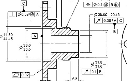
When I locate the datum, especially an axis, I always attach it to a dimension, thereby defining which surface I am using as the datum. It's just like the old days on the drawing board or 2-d cad, you have to convey the information to the inspector. If you have multiple diameters, you have to attach the datum to the diameter you want to use to create the datum.
To steal a little screenshot from ASME, the B and C datums are coincident in theory but are definitely not the same axis

I may be completely off base, if so, please forgive me.
- Mark as New
- Bookmark
- Subscribe
- Mute
- Subscribe to RSS Feed
- Permalink
- Notify Moderator
Oh, don't forget to vote on your own idea. I thought they fixed it so it automatically voted but I guess not.
Steve
- Mark as New
- Bookmark
- Subscribe
- Mute
- Subscribe to RSS Feed
- Permalink
- Notify Moderator
The way I deal with multiple diameters on a common axis, is to create an axis associated to only the diameter that will be my datum. I then attach it to a dimension of FCF in the drawing.


