Community Tip - You can subscribe to a forum, label or individual post and receive email notifications when someone posts a new topic or reply. Learn more! X
- Community
- Creo (Previous to May 2018)
- Creo Modeling Questions
- A Problem on the adjustable screw
- Subscribe to RSS Feed
- Mark Topic as New
- Mark Topic as Read
- Float this Topic for Current User
- Bookmark
- Subscribe
- Mute
- Printer Friendly Page
A Problem on the adjustable screw
- Mark as New
- Bookmark
- Subscribe
- Mute
- Subscribe to RSS Feed
- Permalink
- Notify Moderator
A Problem on the adjustable screw
Hi all
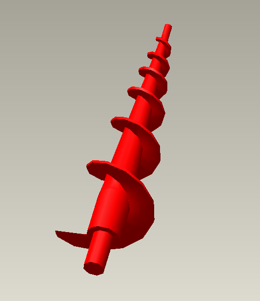
Can anyone tell me how to create the adjustable screw in Pro-E? Does anyone know how to do this now.
Here is the Annex.
I look forward to hearing form you.
Solved! Go to Solution.
Accepted Solutions
- Mark as New
- Bookmark
- Subscribe
- Mute
- Subscribe to RSS Feed
- Permalink
- Notify Moderator
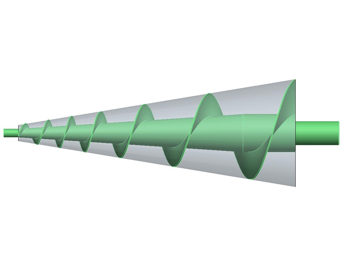
Just another view to show how this correlates with your definition. I also noticed that I had a RH screw; yours is LH. So, a change of the theta definition from t to -t was also made.
- Mark as New
- Bookmark
- Subscribe
- Mute
- Subscribe to RSS Feed
- Permalink
- Notify Moderator
Have you tried using a helical sweep with a variable pitch?
- Mark as New
- Bookmark
- Subscribe
- Mute
- Subscribe to RSS Feed
- Permalink
- Notify Moderator
Yes,I do. But the dimension is different from the label above the dimension of cad drawing.I do not know where the error.
- Mark as New
- Bookmark
- Subscribe
- Mute
- Subscribe to RSS Feed
- Permalink
- Notify Moderator
Looked at your DWG quickly. All the note text was unreadable for some reason, but I could read the drawing. Looked to me as if this was a 2D-only design, because it didn't really look like a view of a full 3D model, yes? If I understand correctly, the spiral is a thin blade of a tapered auger. It also looks as if its section is tapered. As to the variable pitch, the way the drawing is dimensioned doesn't really tell me what's going on. In other words, the pitch could suddenly change to a new value at each of the dimensioned positions (360 degrees of revolution)--which I doubt--or it could be a continuously variable pitch that yields the dimensions shown. Can you clarify this a little bit more???
- Mark as New
- Bookmark
- Subscribe
- Mute
- Subscribe to RSS Feed
- Permalink
- Notify Moderator
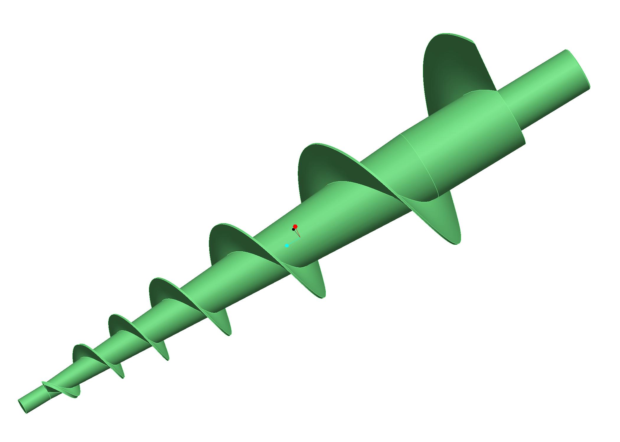
Is this the sort of thing you are trying to do?
- Mark as New
- Bookmark
- Subscribe
- Mute
- Subscribe to RSS Feed
- Permalink
- Notify Moderator
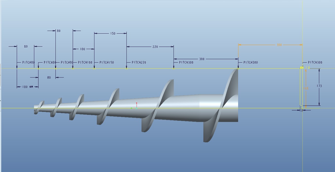
Do you measure the pitch of 3D model Between the pitch of CAD drawing?They are the same pitch it?
- Mark as New
- Bookmark
- Subscribe
- Mute
- Subscribe to RSS Feed
- Permalink
- Notify Moderator
- Mark as New
- Bookmark
- Subscribe
- Mute
- Subscribe to RSS Feed
- Permalink
- Notify Moderator
So, have you solved your problem? If you can use a variable pitch Helical Sweep, as Andrew suggested, that would be easiest. The model pictured above in qreen is quite a bit more complicated to match your dimension scheme. It includes a Graph feature and a pretty funky Equation-driven Curve dependent on the Graph, then a Variable Section Sweep using two trajectories, one on the axis.
- Mark as New
- Bookmark
- Subscribe
- Mute
- Subscribe to RSS Feed
- Permalink
- Notify Moderator
Of course not.Can you share your model to me?
- Mark as New
- Bookmark
- Subscribe
- Mute
- Subscribe to RSS Feed
- Permalink
- Notify Moderator
Here's the idea, using a graph called "A" to capture your dimension scheme. The vertical 100, 200, 300 ... dimensions ultimately represent 360 degree rotation increments when we use the graph in the equation driven curve. I simplified your model a little by assuming it was just 6 full turns, although I can see it is just a little bit more than that.
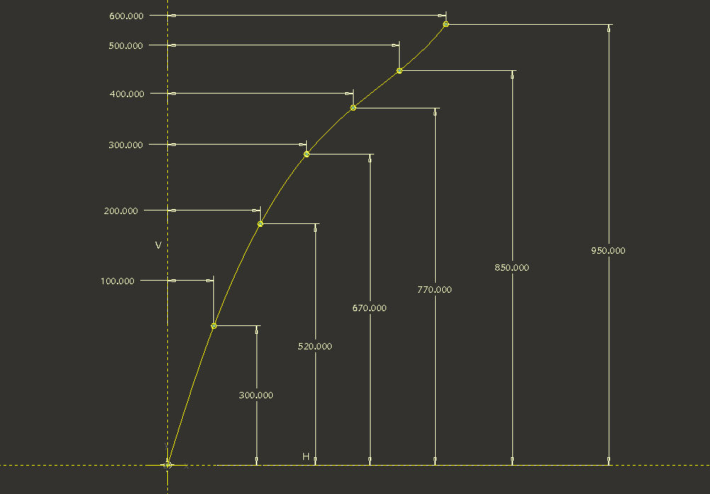
Then we create a Cylindrical Coordinates Curve using the following Equations:
r=185-(157.5*(evalgraph("A",t*600)/950))
theta=t*360*6
z=evalgraph("A",t*600)
- Mark as New
- Bookmark
- Subscribe
- Mute
- Subscribe to RSS Feed
- Permalink
- Notify Moderator
Here's a shot of the resulting curve:
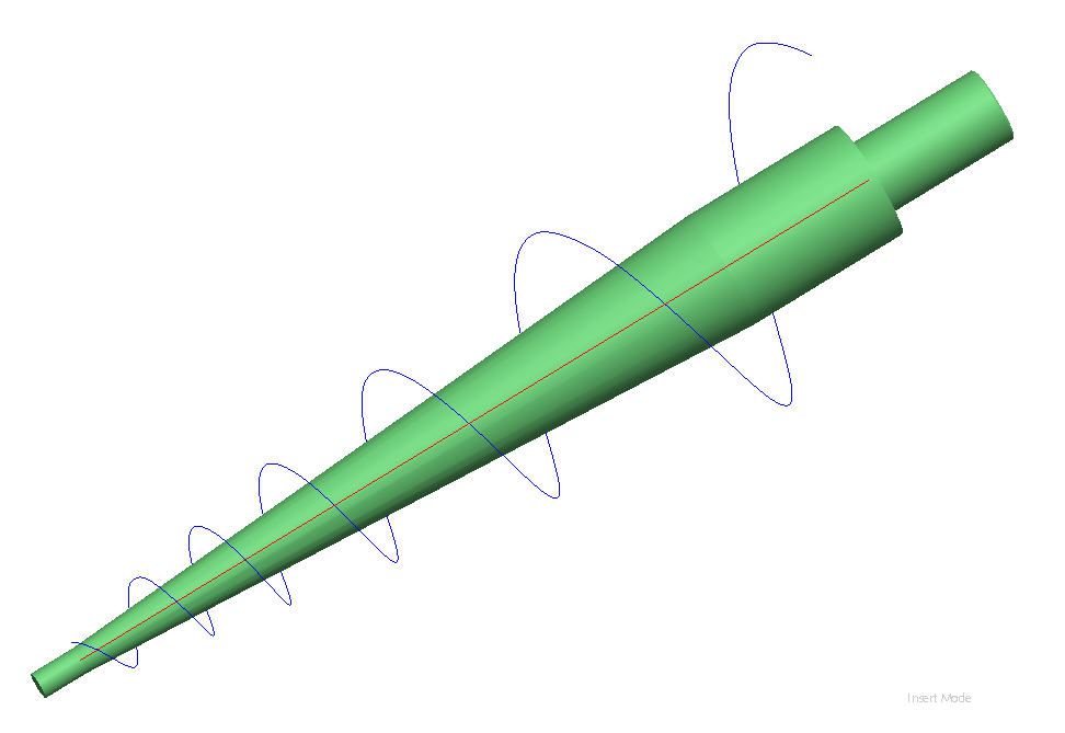
- Mark as New
- Bookmark
- Subscribe
- Mute
- Subscribe to RSS Feed
- Permalink
- Notify Moderator
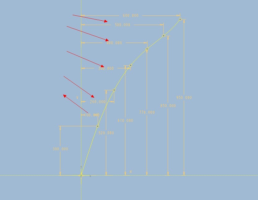 I would like to know the value of the vertical axis is arbitrary above it?
- Mark as New
- Bookmark
- Subscribe
- Mute
- Subscribe to RSS Feed
- Permalink
- Notify Moderator
First of all, here is a correction to the Graph to take into account the fact that you have slightly more than 6 turns of the helix; I have arbitrarily set it to 6-1/4 turns, thus the addition of the 625x950 XY point to the graph. (You also have to replace 6 with 6.25 and 600 with 625 in the curve equations.)
Second, I want to emphasize that I still feel this solution, although interesting and a way to match the dimensions on your drawing, is pretty strange. I don't think it represents an elegant or straightforward 3D design. I don't think those 2D dimensions should drive the design; they should be the result of a simpler 3D definition, again maybe using a variable-pitch helical sweep. Note for example the little dip in the spline on the graph (at XY 500x850); it doesn't look like the result of smooth design intent.
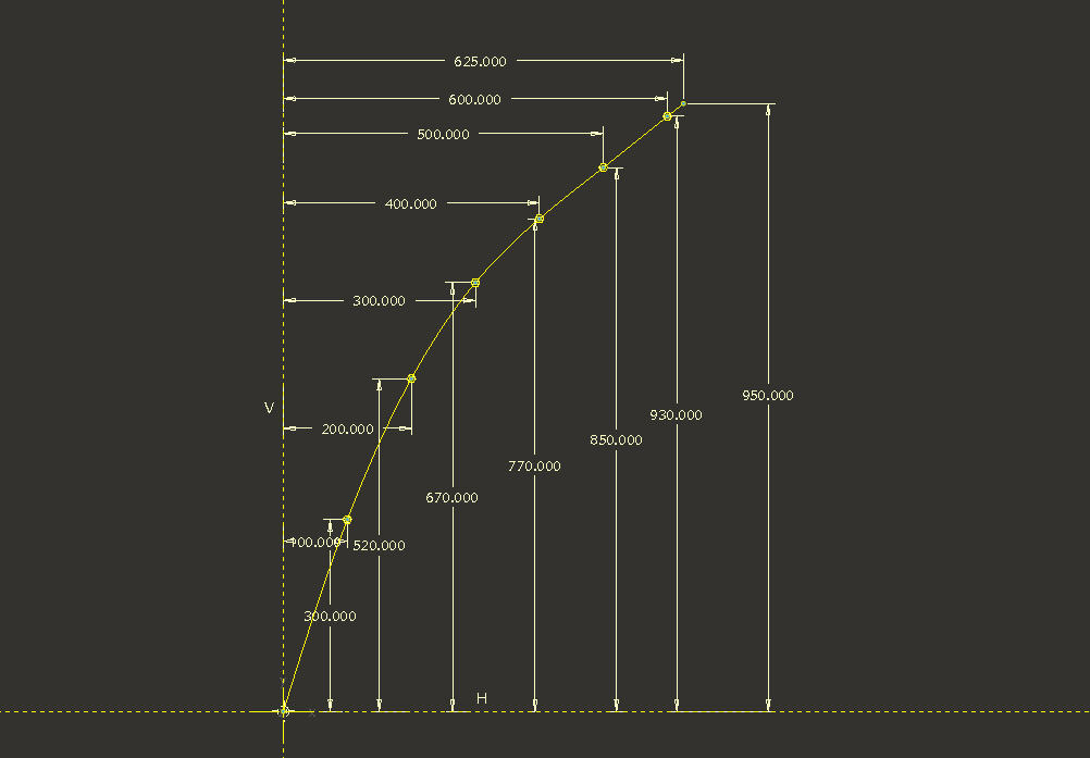
Third, your question. I'm not sure what it is you are asking. Are you referring to the 100, 200, 300 ... dimensions? If so, these should be exact because they are used to drive the value of angular revolution through the "trajpar" relations. If you have not used trajpar and graphs much before, this may be confusing. In theory the values could be 1, 2, 3 ..., but then the graph would look like a long vertical line, and be virtually useless. This is just a scaling factor. It is factored in in the curve equations by multiplying trajpar by 600 (or 625 in the corrected version) for the r & z values. The vertical values are just the result of adding up the spacing dimensions from your drawing (e.g. 520=300+220, 670=520+150, etc.).
I hope this helps, but I still think you should look for a simpler means of defining this model.
David
- Mark as New
- Bookmark
- Subscribe
- Mute
- Subscribe to RSS Feed
- Permalink
- Notify Moderator
P.S. Even changing the Graph to a 3 or 4-point spline (instead of an 8-point spline) would give an improvement in smoothness.
- Mark as New
- Bookmark
- Subscribe
- Mute
- Subscribe to RSS Feed
- Permalink
- Notify Moderator
I am sure all of the dimensions are showing in the drawing on。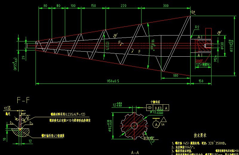
- Mark as New
- Bookmark
- Subscribe
- Mute
- Subscribe to RSS Feed
- Permalink
- Notify Moderator
Just another view to show how this correlates with your definition. I also noticed that I had a RH screw; yours is LH. So, a change of the theta definition from t to -t was also made.

- Mark as New
- Bookmark
- Subscribe
- Mute
- Subscribe to RSS Feed
- Permalink
- Notify Moderator
Here are some images of a model created with a variable pitch helical sweep.
- Mark as New
- Bookmark
- Subscribe
- Mute
- Subscribe to RSS Feed
- Permalink
- Notify Moderator
Can you show all of the pitch in 3D model?
- Mark as New
- Bookmark
- Subscribe
- Mute
- Subscribe to RSS Feed
- Permalink
- Notify Moderator

