Community Tip - Learn all about PTC Community Badges. Engage with PTC and see how many you can earn! X
- Community
- Creo (Previous to May 2018)
- Creo Modeling Questions
- An Interesting SPR Concerning Beams
- Subscribe to RSS Feed
- Mark Topic as New
- Mark Topic as Read
- Float this Topic for Current User
- Bookmark
- Subscribe
- Mute
- Printer Friendly Page
An Interesting SPR Concerning Beams
- Mark as New
- Bookmark
- Subscribe
- Mute
- Subscribe to RSS Feed
- Permalink
- Notify Moderator
An Interesting SPR Concerning Beams
A few weeks ago, a customer filed an SPR about some beam results. In it, the customer asked why Simulate produced very different results for three different models that seemed nearly identical. It took me a while figure out all the reasons, some of which turned out to be fairly subtle. This blog post gives a pretty complete explanation, and touches on the following topics, which may be of general interest:
- Asymmetric beams
- Creo Simulate's multiple beam coordinate systems
- Shear center
- Solid sketched sections
- Weighted links
- Total Load at Point
tl;dr : Simulate computes correct results, but you have to be careful when using solid sketched beam sections.
Problem Statement
The short description of the SPR states:
"max disp mag" value is unexpectedly too high compared to theoretical results when using a 3D Model or a beam with standard section in Creo Elements/Pro Simulate 5.0
The problem to be solved is about as simple as it gets: a cantilever beam with a load on the end.
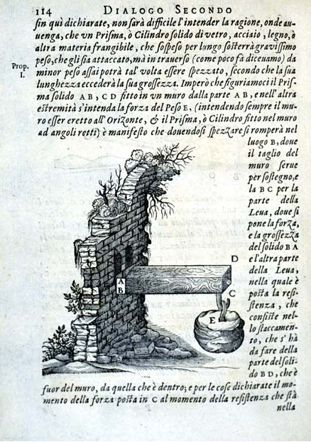
Figure 1
Unlike this beam from Galileo's Discorsi e dimostrazioni matematiche, intorno à due nuoue scienze, the customer's beam has a channel section and is made of aluminum.
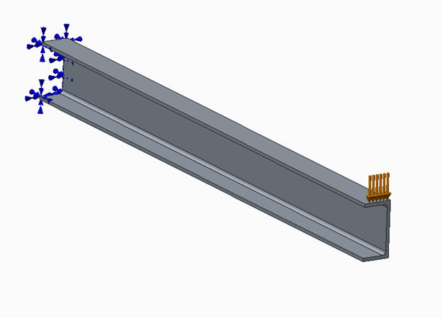
Figure 2
The user provided three different, but equivalent models to represent the situation:
- A beam model with a standard channel section,
- A beam model with a solid sketched section
- A 3D solid model (shown above in figure 2)
The beam's length, L, is 2 m. The channel section has the following dimensions.
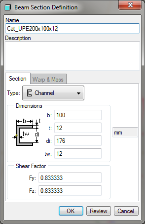
Figure 3
The Young's modulus is 70 GPa and the applied load is 6375 N.
A simple hand calculation using strength of materials beam theory gives the end deflection as
d = P L^3 / (3 E I) = 9 mm
When the customer ran the analysis with Simulate, he got the following values for the measure max_disp_mag:
Model | max_disp_mag (mm) |
beam with channel section | 31 |
beam with sketched section | 9 |
3D solid | 27 |
So at first glance, it looks like Simulate is giving the correct results for the beam with the sketched section but not for the others. Is that really the case?
Actually, Simulate is computing accurate results, and the explanation follows. But first, some background information…
Preliminaries
When using Simulate, there are two local coordinate systems associated with a beam section: shape, and principal.
Shape Coordinate System: The shape coordinate system is the one that is used to define shape or outline of the beam's cross-section. It is also the one that is drawn in the model window. Here's one for a channel section:
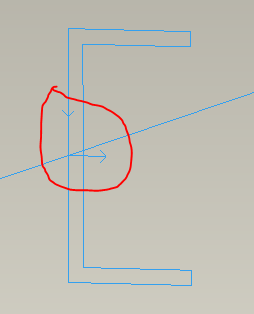
Figure 4
Here, the arrow pointing to the right is the shape Z-direction, and the other vertical arrow, with the upside down arrow head, is the shape Y-direction. (It looks like the letter Y, get it?) These arrows meet at the origin of the shape coordinate system. (The blue diagonal line is the curve that the beam references.)
Here are similar figures for rectangular and circular sections.
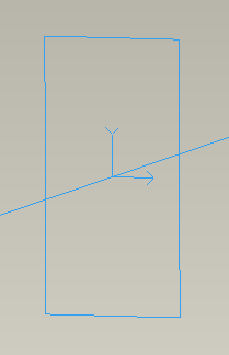
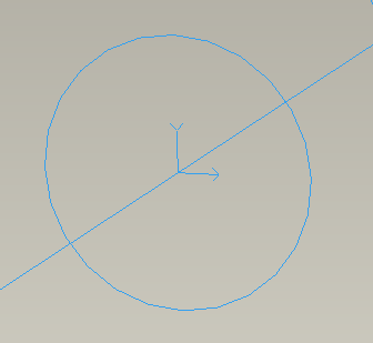
Figures 5 & 6
Principal Coordinate System: (The definition of this CS isn't really pertinent to the issue at hand, but I included it for completeness. You can skip this section if you want.) The principal coordinate system is defined by the shape of the section. Its origin is at the centroid of the section and its axes point in the principal directions of the beam section. The principal directions are special in that a moment applied about one of the principal axes results in bending about only that axes.
For the rectangular and circular sections in Simulate, the principal CS coincides with the shape CS. For the channel section, the principal CS is shown below.
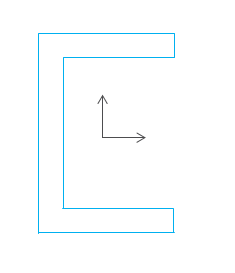
Figure 7
In all of the above cases, the principal axes happen to be parallel to the shape axes, but that is not the case for all beam section shapes. For example for an L-section, the shape CS origin is not at the centroid, nor are its axes aligned with the principal axes.
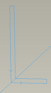
Figure 8
Shear center: (Don't skip this section. It's important.) There is another beam section point that strongly influences the beam's behavior: the shear center. The section's shear center is defined to be that special point at which applied forces induce no twisting of the beam. Loads applied offset from the shear center will induce twisting. For doubly symmetric beam sections, the shear center and centroid coincide. For the channel section, the shear center is located at the red dot shown below.
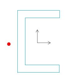
Figure 9
Action Coordinate System: When a beam idealization is defined for a model, the user references geometry (curves or points) on which to place the beam. The location of this geometry defines the action coordinate system for the beam. The beam's action coordinate system origin is the location where
- forces and moments are transmitted to and from the beam to the rest of the model
- loads (forces and moments) are applied
- displacement and rotation results are reported
By default, the shape origin coincides with the action origin, as shown in figures 4, 5, 6 & 8. The user can choose to position the beam section relative to the action origin by defining a "beam orientation". The user can chose to define either the shape origin or the shear center with respect to the action coordinate system.
In the customer's model with the channel section, the user defined the beam orientation so that the loads are applied to the center of the top flange.
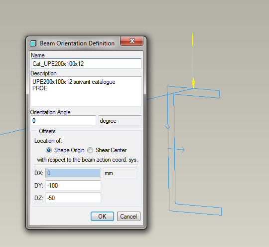
Figure 10
Note that the beam's reference curve and the applied force vector intersect.
With this information, we can now discuss the customer's thee models.
Beam Model with the Standard Channel Beam Section
Mechanica reports
- max_disp_mag = 31 mm, and
- max_disp_y = -24.5 mm
Because, max_disp_mag > |max_disp_y|, the end of the beam must be deflecting not just in the –Y direction.
(Remember, the expected result is approximately -9 mm).
The beam section definition dialog for the standard channel section is shown in below…
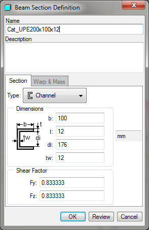
Figure 11
… and its properties are shown when you press the Review button.
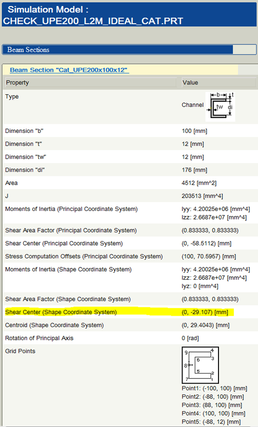
Figure 12
Note that the shear center is located at (0, -29.107) mm, measured in the shape coordinate system, as shown below.
Because the user did not align the beam's shear center with the action origin (compare figures 9 & 10), the applied load does not pass through the shear center and therefore when the beam is loaded, it both deflects and twists about the shear center. As described above, Simulate reports displacement and rotation results at the action origin. The action origin is moving due to both the downward deflection of the beam and the twisting of the beam about the shear center.
The standard hand calculation for the deflection of a cantilever beam
d = PL^3/(3EI) = 9 mm
computes the displacement of the shear center, which if the beam twists, is not the same as the displacement of any another arbitrary point on the beam section.
For comparison, we need to compute the deflection of the shear center from the Simulate results, as follows. The shear center is located -29 mm relative to the shape origin (see figure 12), which is -50 mm relative to the action origin (see figure 10). So the shear center is located -79 mm relative to the action origin. Simulate computes that the action origin at the end of the beam rotates -0.188 radians about the z axis and deflects -24.1 mm in the y direction.
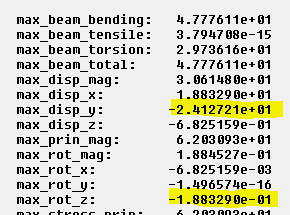
Figure 13
Therefore the shear center deflects
-24.1 mm + (-79 mm * -0.188) = -9.2 mm
[The small discrepancy between the Simulate results (-9.2 mm) and the standard hand calculation (-9.0 mm) is due to the difference in the theories used. The customer's hand calculations used the standard strength of materials theory while Simulate uses the Timoshenko beam theory, which accounts for shear deformation.]
Another way to obtain the customer's expected theoretical result is to load the beam at the shear center, by defining the beam orientation to locate the shear center at the action origin, as shown below.
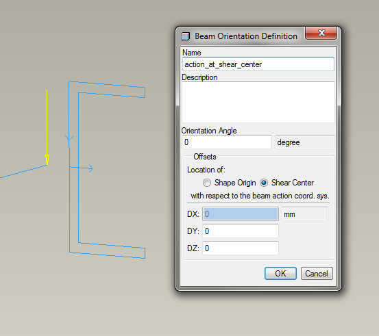
Figure 14
Notice how the reference curve and the applied load pass through the shear center. Running Simulate gives the same result as before, max_disp_y = -9.2 mm
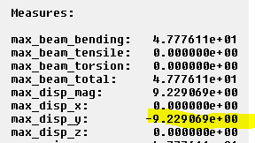
Figure 15
Beam model with the solid sketched section
This model looks nearly identical to the first…
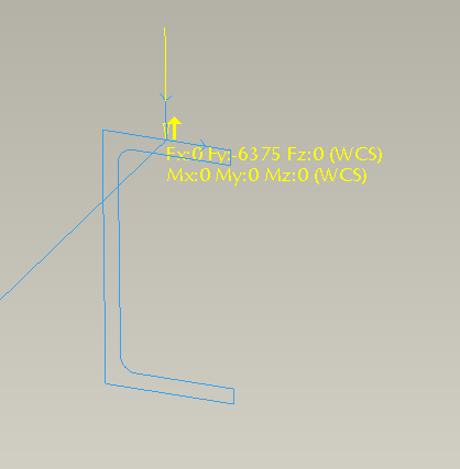
Figure 16
but it gives entirely different results. In fact, for the deflection at the end of the beam, it gives the elementary beam theoretical result: -9 mm.
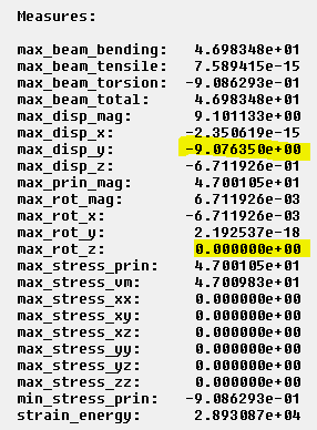
Figure 17
Why is that?
When editing the sketched section, this dialog appears:
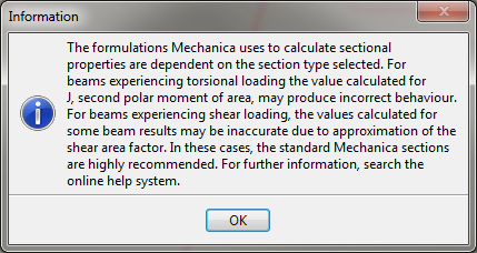
Figure 18
As we know from the previous results, the beam we are modeling is in fact "experiencing torsional loading", because the applied load does not pass through the shear center, so this dialog is warning us that the results may not be accurate. Reviewing the section properties…
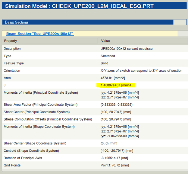
Figure 19
…we see that the second polar moment of inertia (J = 1.4e7), is much greater than that of the standard channel section (J = 2.0e6, from figure 12). So the warning message was correct and important. Also, notice that there is no entry for the location of the shear center. Simulate cannot calculate the shear center for solid sketched sections. (It can for thin sketched sections.) It is up to the user to enter that value on the Beam Section Definition dialog. In the customer's model, the shear center was set equal to zero:
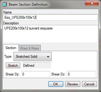
Figure 20
Therefore, now we know why the model with the sketched section gives results that appear to agree with simple beam theory. Simulate thinks that the shear center of the beam is the same as the action origin (even though in reality it isn't.) Hence, Simulate ignores the moment induced by the applied force because it thinks the force goes through the shear center. As a result, the beam does not twist (max_rot_z = 0, in figure 17) and the computed displacement of the action origin is not affected by any rotation. So the displacement computed at the action origin (and supposed shear center) matches the hand calculation for the shear center.
Suppose we try to correct this error by entering the correct values for shear center on the Beam Section Definition dialog in order to reproduce the results obtained by the first model. Unfortunately, Simulate will not compute the correct results because the value for J is much too high.
The main take-away from this example is: it's best to not use solid sketched sections for asymmetric beams.
(Note: It is OK to use thin sketched sections for asymmetric beams because in this case, Simulate can compute the shear center.)
3D model
The 3D model captures all effects and this (magnified) deformed view of the displacement magnitude clearly shows that the beam is both deflecting and twisting.
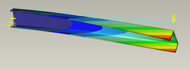
Figure 21
Here are some numerical values of the y component of displacement.
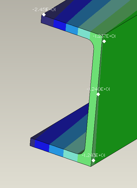
Figure 22
In order compare the results for the solid model with the results for the two previous beam models, we must compute the deflection of the shear center. But how do we do that if the shear center is a point floating in space, not connected to the model? Here's one way.
- Create a datum point at the location of the shear center. (Here we are using the shear center computed for the standard section from figure 12. The standard section is nearly identical to the section of the solid model, but not exactly.)
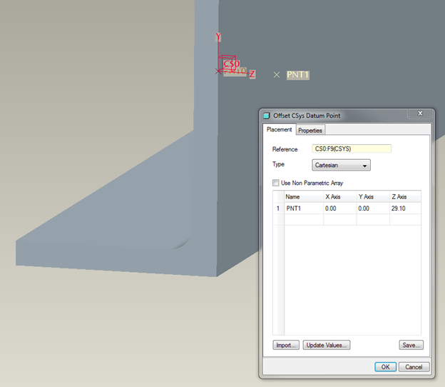
Figure 23
- Tie the movement of this datum point to the movement of the beam's web with a weighted link.
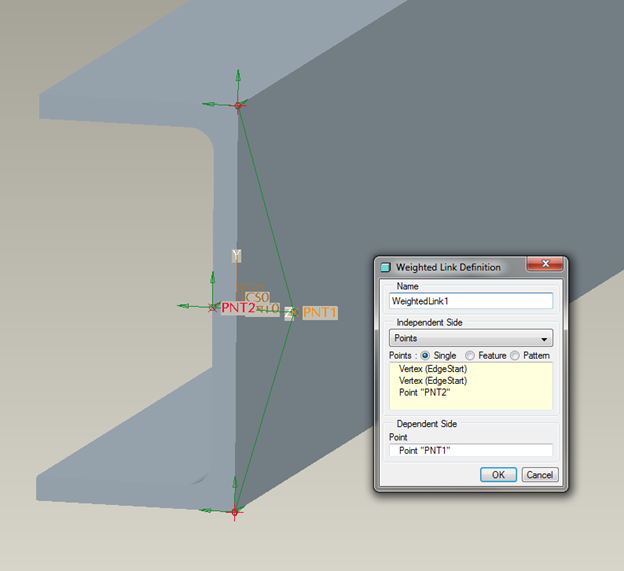
Figure 24
- Create a displacement measure on the datum point.
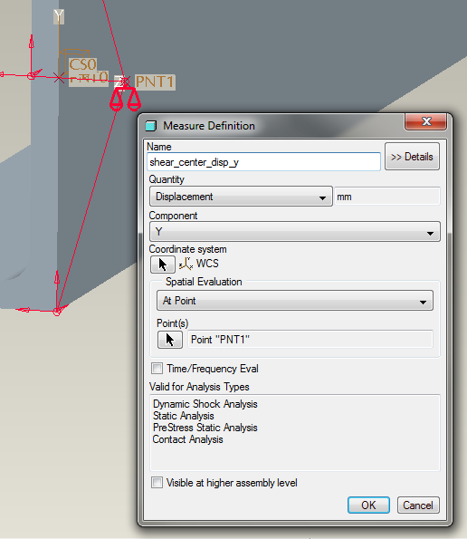
Figure 25
Running the analysis gives the expected result:
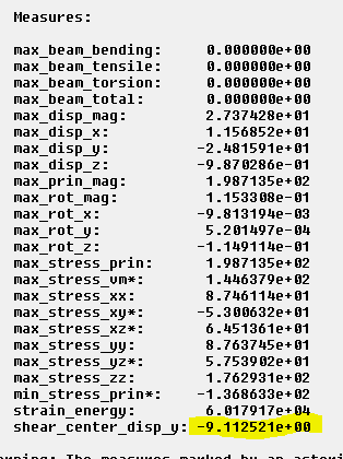
Figure 26
As a final example, let's see what happens when you load the solid beam at the shear center. To do so, we could either create a weighted link, say between the shear center and the end of the beam, or we could create a total load at point. We'll choose the later, just for variety's sake.
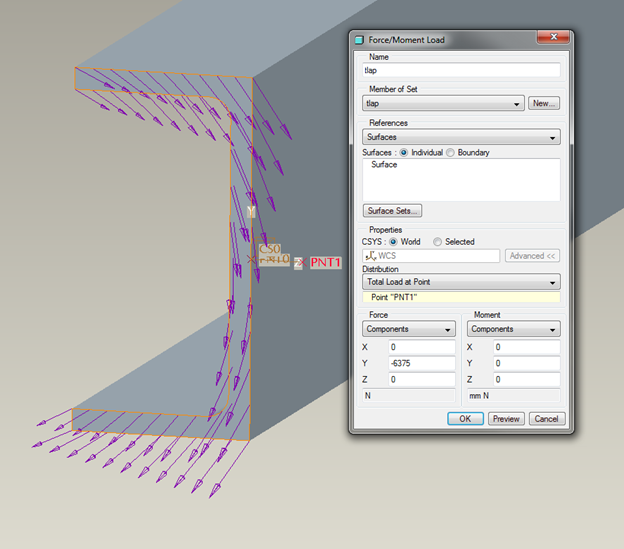
Figure 27
Notice that a force applied to the shear center is equivalent to a force and moment applied over the end surface of the beam.
Running the analysis gives the expected results for displacement
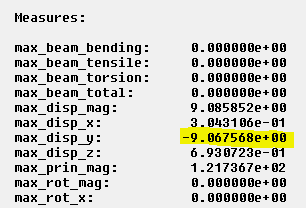
Figure 28
And we can see that the beam doesn't twist (compare with figure 21).
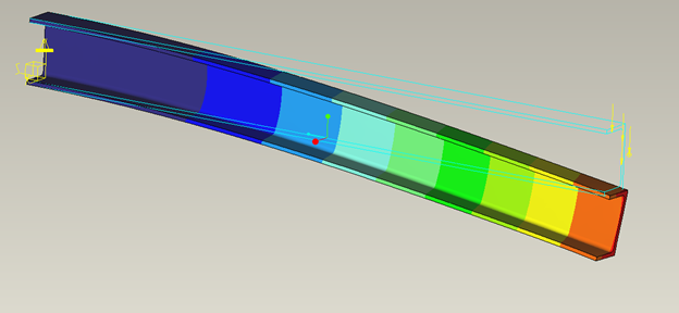
Figure 29
In conclusion, we see that when we analyze a cantilever beam having a channel section, we can either model it as 3D solid or as a beam with a standard channel section. The results from these models are consistent with each other and with results calculated with standard elementary beam theory. We also see that the warning message about using an asymmetric solid sketched section should be heeded, as the results may be inaccurate in this case.
- Mark as New
- Bookmark
- Subscribe
- Mute
- Subscribe to RSS Feed
- Permalink
- Notify Moderator
Hi Tad,
I was trying to reoncile the Pro/E cross section mass properties calculation and the Mechanica beam section calculation for polar moment, J.
For the channel section I get :
Mechanica standard channel - 203513 mm^4, just as you did.
From Pro/E mass properties I get :
Cross section polar moment - 3.0887231e7 mm^4 calculated at the COG/Principal csys
Cross section polar moment - 3.4788352e7 mm^4 calculated at the shape csys
Of course the value of J changes with change of csys; it's the difference between Pro/E mass properties and Mechanica I don't understand.
Can you unravel my thoughts?
Thanks
Charles

