1-Visitor
November 24, 2013
Solved

Scissor and Slot/Slider Mechanism Combo

  • November 24, 2013
  • 1 reply
  • 12078 views

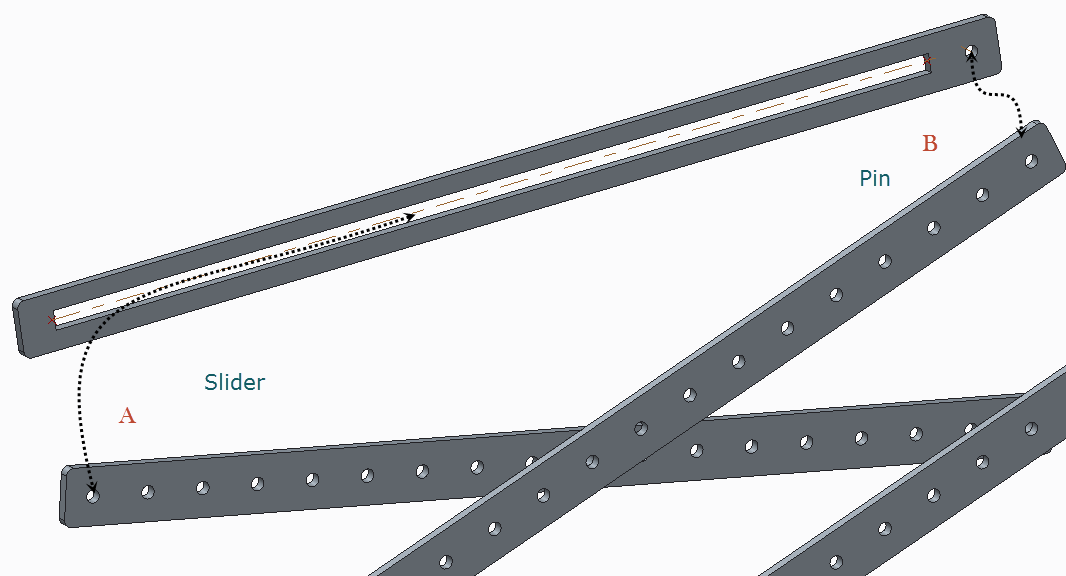
Pictured is the top part of our scissor mechanism. There's a Pin constraint at every joint where the beams intersect. They work fine and 'scissor' as expected.

Now I want to attach the beam with the slot and hole in in such that it's Pinned to one scissor beam (at B) and a peg in the other beam (A) slides through the slot as the scissors expand/contract.

I've been at this for a while and just can't get it - usually I can't get past 'connection definition is incomplete' sort of messages. If I do get past that it just doesn't do much of anything.

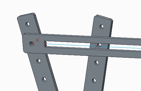
I've tried Slot and Slider constraints on A using the hole on the scissor beam and putting an axel through it and using that.

I've defined an axis and planes but they're not taken as valid selections while defining the constraints. This makes me wonder if I'm just doing something fundamentally wrong - I'm not a mechanical engineer type.

Thanks,

Dan Holt

FTC 7300 Mentor

ScissorSlideQuestion.png

    Best answer by sm_01

    Dan,

    You were pretty close. I only adjusted three things.

    1. Created a Sketched Curve in the slot model intead of point-point.
      (not sure if that was required, but wanted to rule it out)
    2. Created an offset point in the arm model to align with the sketched curve in the slot model.
    3. Changed the assembly units to MM

    slot.png

    It moves a little funky becuase the first component is placed as a Default, locking it into position. In my example, I used the slot model as the first component and then added the cross members to it. That kept the lifting cross linked into the slot model. Hope this helps

    1 reply

    1-Visitor
    November 24, 2013

    Dan, if you want to send me the models, I can take a look at it. If you ZIP it up and put it in the CAD folder of your Windchill project, I could pick it up from there. Sounds like you are pretty close. To use the Slot connection, you'll need a datum curve and a datum point. I would suggest putting a datum curve down the center of your slot. Then create a datum point at the center of A, but offset enough to be coincident with the curve when assembled (or on the mating surfaces).

    1-Visitor
    November 24, 2013

    Dan, I was able to create something similar this morning. Not sure if its exactly the same, but should be in the ball park. I have uploaded the models as a new document if you want to download and check them out.

    scissor.png

    1-Visitor
    November 24, 2013

    Patriots are not playing till 8:00pm tonight and its really cold out today. So, I added some hardware and made it a lttle more realistic. I'm not a scissor lift specialist by any meams, but this is much better than the first model. I tend to skip all the required hardware and fasteners for the initial concept and then find they drive the final design once you have them all in there.

    I decided to go with a binding post as a connection simply becuase it was the smallest form factor. I found them also referred to as screw posts, barrel nuts, sleeve nuts and connector nuts. I'm assuming if you buy these in stainless they would be rugged enough for this type of scissor lift, but have never built this for real. Curious to hear how other teams have constructed these in the past?

    The download referenced previously has been updated with the new model.

    scissor.png