Community Tip - When posting, your subject should be specific and summarize your question. Here are some additional tips on asking a great question. X
- Subscribe to RSS Feed
- Mark Topic as New
- Mark Topic as Read
- Float this Topic for Current User
- Bookmark
- Subscribe
- Mute
- Printer Friendly Page
ABOUT UDF'S
- Mark as New
- Bookmark
- Subscribe
- Mute
- Subscribe to RSS Feed
- Permalink
- Notify Moderator
ABOUT UDF'S
hello,
is it possible to create an udf that changes as the principal model?
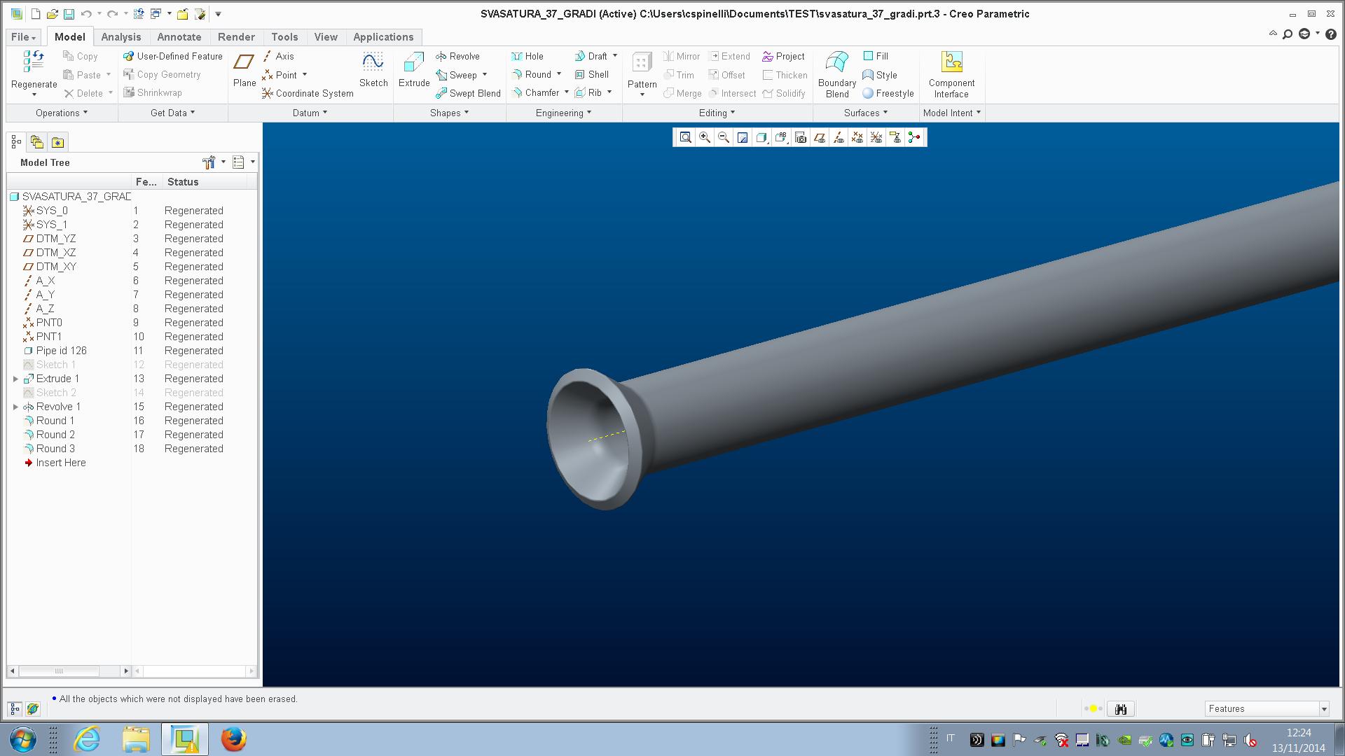
let me explain: i have a pipe and, in the end of it, i want to use an udf to add a countersink.
this countersink changes with the dimension and thickness of the pipe.
is it possible?
This thread is inactive and closed by the PTC Community Management Team. If you would like to provide a reply and re-open this thread, please notify the moderator and reference the thread. You may also use "Start a topic" button to ask a new question. Please be sure to include what version of the PTC product you are using so another community member knowledgeable about your version may be able to assist.
- Labels:
-
2D Drawing
- Mark as New
- Bookmark
- Subscribe
- Mute
- Subscribe to RSS Feed
- Permalink
- Notify Moderator
Hello Christian,
l think it´s a problem about refernece selection. You have to know what you want, than create en UDF. l prepared an example for you. Please see attached file:
There are 3 featers:
1. PIPE - extrude feater for modifications (try to edit and see next 2 revolts featers what they do)
2. DYNAMIC - revolte feater that works with modified pipe diameter and wall thickeness
3. STATIC - revolte feater that is OK in "start" dimmensions, but with PIPE modifications it starts to be a mess.
l think something like DYNAMIC feater is what are you looking for.
Hope it help
Regards
Milan
- Mark as New
- Bookmark
- Subscribe
- Mute
- Subscribe to RSS Feed
- Permalink
- Notify Moderator
thanks, but i meant another question, as seen in the image attached.
i have a pipe diameter 6 thickness 1 and i added a countersink with an udf.
i want to be able that, if i change the diameter or thickness of the pipe, automatically changes the udf

- Mark as New
- Bookmark
- Subscribe
- Mute
- Subscribe to RSS Feed
- Permalink
- Notify Moderator
From what I see here, I don't understand why you used a UDF in the first place. I always look on UDF functionality as a "I have to do this dozens of times and it is incredibly tedious" tool. What you show here looks like a simple revolved feature, but maybe I'm just jumping to conclusions.
Either way, what you should probably look into is using relations to set the dimensions of the countersink. You use the dimension that defines the pipe diameter (inner, outer, both) and use calculate the countersink dimensions based upon whatever criteria you would use to hand calculate it.
- Mark as New
- Bookmark
- Subscribe
- Mute
- Subscribe to RSS Feed
- Permalink
- Notify Moderator
yes, you're right but the people i work with are very "bithcy" about that...
they said to me "i want to work as less as possible"..
so, in your opinion, can i use a relation like "IF DIAMETER = 6 THEN DIMENSION IS.."?
- Mark as New
- Bookmark
- Subscribe
- Mute
- Subscribe to RSS Feed
- Permalink
- Notify Moderator
From what I remember about UDF building, it's not really amenable to using relations. I think what you might need to do is define a UDF for each standard size pipe you use. Hopefully there aren't too many.
- Mark as New
- Bookmark
- Subscribe
- Mute
- Subscribe to RSS Feed
- Permalink
- Notify Moderator
you can make the UDF have a variable dimension so when the user brings the UDF in they would be prompted for what the diameter of the shaft is.
- Mark as New
- Bookmark
- Subscribe
- Mute
- Subscribe to RSS Feed
- Permalink
- Notify Moderator
But I think the crux of the problem is that we wish to use the pipe diameter to calculate the other dimensions for the feature. From what I remember, relations are not available in UDFs. Thus, I think you'd need to define a UDF for the different sizes of pipe you expect to use. One for each size, unfortunately. Either that or you make all the dimensions of the thing variable and rely on someone entering all of them correctly every time they use the UDF.
- Mark as New
- Bookmark
- Subscribe
- Mute
- Subscribe to RSS Feed
- Permalink
- Notify Moderator
This is very doable. There are basically two approaches.
- Make one (or more) dimensions or parameters variable when creating the UDF. This will allow the user to enter a value (like pipe size) when placing the UDF and have it update accordingly.
- Create a feature to "measure" the pipe and then build your countersink feature off of that. There is no problem with putting relations inside the features that make up the UDF group.
This second approach works great when you need the new feature to be driven by the location and/or size of something else. I've used this in the past to make dependent hole features (clearance holes, tapped holes, counter bores, etc.)
Regardless of which approach you take, be very careful what references you choose. Any reference that any feature has to anything outside the group will require selection when placing the UDF. (Planes, edges, faces, etc.) Strive to build the features and the UDF with the minimum amount of references possible.


