Community Tip - If community subscription notifications are filling up your inbox you can set up a daily digest and get all your notifications in a single email. X
- Community
- Creo+ and Creo Parametric
- 3D Part & Assembly Design
- Axis pattern fails to regenerate
- Subscribe to RSS Feed
- Mark Topic as New
- Mark Topic as Read
- Float this Topic for Current User
- Bookmark
- Subscribe
- Mute
- Printer Friendly Page
Axis pattern fails to regenerate
- Mark as New
- Bookmark
- Subscribe
- Mute
- Subscribe to RSS Feed
- Permalink
- Notify Moderator
Axis pattern fails to regenerate
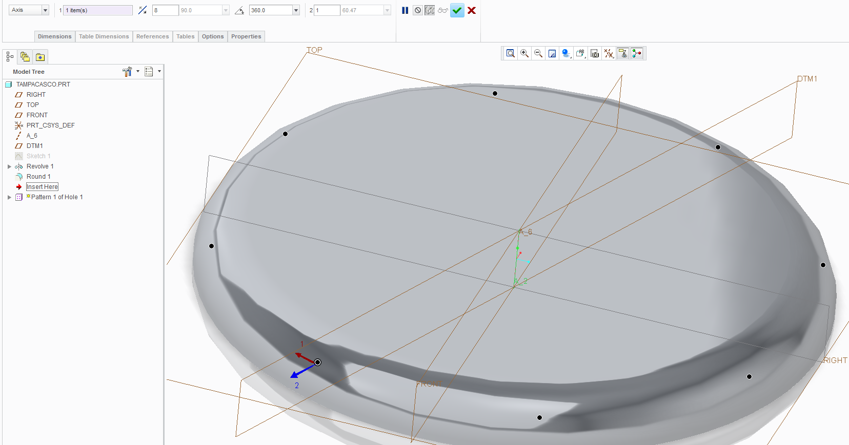
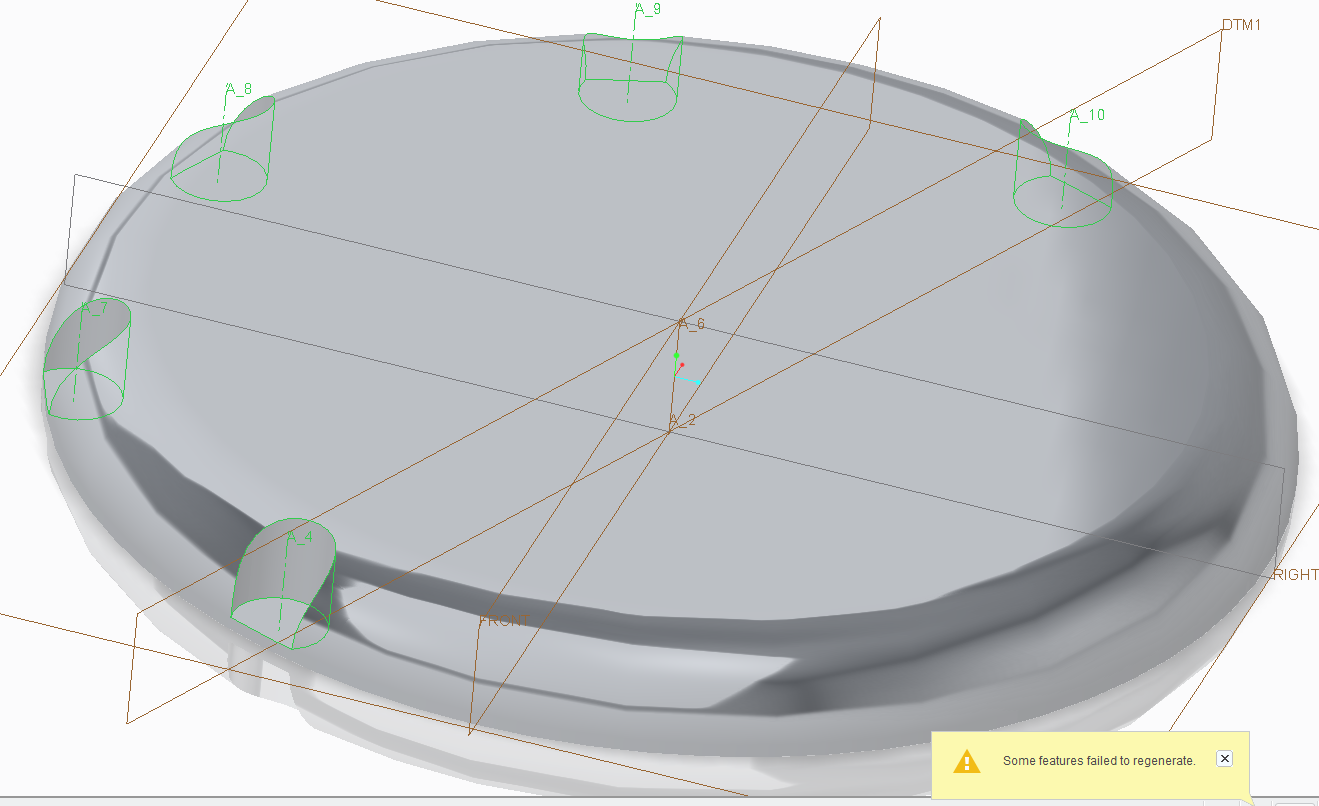
For apparent no reason
Check my screenshots and tell me if I'm trying something beyond logic
The angle of that funky datum is 22.5º


This thread is inactive and closed by the PTC Community Management Team. If you would like to provide a reply and re-open this thread, please notify the moderator and reference the thread. You may also use "Start a topic" button to ask a new question. Please be sure to include what version of the PTC product you are using so another community member knowledgeable about your version may be able to assist.
Solved! Go to Solution.
- Labels:
-
General
- Tags:
- regeneration
Accepted Solutions
- Mark as New
- Bookmark
- Subscribe
- Mute
- Subscribe to RSS Feed
- Permalink
- Notify Moderator
you can replace the hole depth reference by a datum point reference.
this way you can control the depth of the hole if you change the round radius if that is your design intent.
otherwise simply entering the depth value can also solve the problem.
- Mark as New
- Bookmark
- Subscribe
- Mute
- Subscribe to RSS Feed
- Permalink
- Notify Moderator
This should work, however, it's hard to say without actually having your model to examine. can you share it?
I suspect your dimensioning/reference scheme falls apart when the pattern instance crosses the 180 degrees of rotation...
Out of curiosity, does it fail if your pattern of 8 holes goes through 175 degree rotation?
- Mark as New
- Bookmark
- Subscribe
- Mute
- Subscribe to RSS Feed
- Permalink
- Notify Moderator
Lucas,
I think you do not need DTM1 because you can relate hole to one of default planes and use Radial placement option.
If you want to use DTM1 then create it as internal feature during Hole creation. You can investigate my Creo Parametric 2.0 model.
Martin Hanak
Martin Hanák
- Mark as New
- Bookmark
- Subscribe
- Mute
- Subscribe to RSS Feed
- Permalink
- Notify Moderator
Paul is correct.
Before it reaches 180 degrees, there is no failure. No matter how many instances.
360 degrees works with a maximum of 3 instances
Martin,
I did that extra plane to see if I could overcome the problem
Before that, I did have a radial thing, similar to yours.
The difference is that I've made 22.5º from a default datum. You've done 0º from an angled datum.
Here's the file
- Mark as New
- Bookmark
- Subscribe
- Mute
- Subscribe to RSS Feed
- Permalink
- Notify Moderator
you can replace the hole depth reference by a datum point reference.
this way you can control the depth of the hole if you change the round radius if that is your design intent.
otherwise simply entering the depth value can also solve the problem.
- Mark as New
- Bookmark
- Subscribe
- Mute
- Subscribe to RSS Feed
- Permalink
- Notify Moderator
Lucas,
it loooks like the problem is related to depth reference of the hole. The funny thing is that I copied the edge into a curve and used the curve as depth reference and pattern works well ![]() .
.
Martin Hanak
Martin Hanák
- Mark as New
- Bookmark
- Subscribe
- Mute
- Subscribe to RSS Feed
- Permalink
- Notify Moderator
Hi Lucas, I can't really explain the 180degree thing, but I suspect it's related to the annoying issue with Creo modeling engine - the way circles and cylinders are always split into 2 halves... Without knowing how the PTC programmers implemented the axial pattern, it just seems that in your case the hole depth reference is "lost" once instance crosses the 180degree point because that's were it will be over the "unselected" part of the circular edge you used for the depth reference.
This example is worth pointing out to PTC, and I really think Creo should not force the user to work with these 1/2 entities - I mean, when do you ever need to reference only 1/2 of the circle/cylinder????
The others gave you some valid work-arounds - by changing the hole depth reference.
Another one is to change the pattern type from "General" to "Variable".
- Mark as New
- Bookmark
- Subscribe
- Mute
- Subscribe to RSS Feed
- Permalink
- Notify Moderator
Excellent explanation, Paul
Twice stupid from PTC's part
First, for slicing the circle in two for no reason
Second (forgivable, actually), for not understanding that when I select that edge, I'm trying to refer to the height it stands on, not the edge itself.
(Or not understanding that the other edge is just a perfect continuation/segment of the previous)
Thank you all guys
Rohit, Martin and Paul
Your tips of auxiliary data resolve the problem with success and elegance.
- Mark as New
- Bookmark
- Subscribe
- Mute
- Subscribe to RSS Feed
- Permalink
- Notify Moderator
i think its your depth reference of hole which is causing the pattern failure. it works if you enter the required depth value oh hole directly.


