Community Tip - Stay updated on what is happening on the PTC Community by subscribing to PTC Community Announcements. X
- Community
- Creo+ and Creo Parametric
- 3D Part & Assembly Design
- Cabling - Auto-populated wire run list
- Subscribe to RSS Feed
- Mark Topic as New
- Mark Topic as Read
- Float this Topic for Current User
- Bookmark
- Subscribe
- Mute
- Printer Friendly Page
Cabling - Auto-populated wire run list
- Mark as New
- Bookmark
- Subscribe
- Mute
- Subscribe to RSS Feed
- Permalink
- Notify Moderator
Cabling - Auto-populated wire run list
I have been doing battle with Pro/Cabling and have now run out of steam.
I have managed to define a couple of connectors, complete with entry ports and pin numbers, created a network and autorouted my cable using the NWF file as recommended.
So far, so good.
I have created a flat harness drawing, with conductor lengths, etc., but I now want to create a wire run list.
I have so far failed to manage this part of the job. I have a repeat region showing one of the connectors and its entry port names together with the wire names attached to each of those entry ports. I cannot get the table to pick up the 'TO' connector/pins, or to read the colour information from the spool definitions included in the NWF file.
I would appreciate any help you are able to offer.
WF4 (!) M220
Regards,
John
This thread is inactive and closed by the PTC Community Management Team. If you would like to provide a reply and re-open this thread, please notify the moderator and reference the thread. You may also use "Start a topic" button to ask a new question. Please be sure to include what version of the PTC product you are using so another community member knowledgeable about your version may be able to assist.
- Mark as New
- Bookmark
- Subscribe
- Mute
- Subscribe to RSS Feed
- Permalink
- Notify Moderator
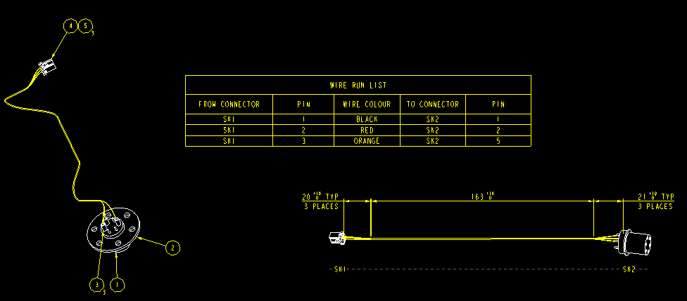
This is the sort of thing I want to achieve, but in this case, the table was created manually in Excel and copy/pasted.
I thought there must be a way to create such a table automatically in Pro/E.
I suppose the lack of answers means either it can't be done, or it's so simple and straightforward that it doesn't warrant a reply...
Seriously, though, any hints, anybody?
Cheers,
John
- Mark as New
- Bookmark
- Subscribe
- Mute
- Subscribe to RSS Feed
- Permalink
- Notify Moderator
John
Please take a look at this thread http://communities.ptc.com/message/259128#259128 Download the zip file and you should be able to investigate all the tables and then create the table you want using the sample tables as a reference.
cheers, Jim
- Mark as New
- Bookmark
- Subscribe
- Mute
- Subscribe to RSS Feed
- Permalink
- Notify Moderator
Jim,
Thank you for the link.
I am unable to use it, because I am using Wildfire 4, so I cannot open Creo 2 files.
Cheers anyway.
John
- Mark as New
- Bookmark
- Subscribe
- Mute
- Subscribe to RSS Feed
- Permalink
- Notify Moderator
John Wayman wrote:
Jim,
Thank you for the link.
I am unable to use it, because I am using Wildfire 4, so I cannot open Creo 2 files.
Cheers anyway.
John
Still no luck after spending another whole day trying.
You have to love the 'friendly as a cornered rat' style of User Interface.
I have created a .NWF file (attached), which tells Pro/E which spools to use, which connectors to use, which pins of which connector, which entry ports of each connector, which to connect ('attach') to which and almost every conceivable cable or wire parameter. I create a table and use &harn.run.from.conn.name to display (I thought) the names of the connector at the 'from' end of the cable and, apparently, there is no connector.
But there it is in the .NWF file. There it is in the 3D model. Not a glimpse in the flattened harness.
The auto-route thing works well, it creates a nice shiny 3D model that looks OK in my assembly. I thought that would be the hard bit.
In real-life, however, I need to be able to tell someone how to make the flat harness, using a drawing and a run table.
Who would have thought that this apparently simple final step would be so difficult?
I'm sure it's ridiculously easy in Creo 3.0, but I don't need you to tell me that...
Is there actually a way to achieve the table I showed above, using a repeat region, in Wildfire 4? If the answer is 'Yes', then how?
Wildfire 4, M220, including the Cabling module.
Thanks,
John
- Mark as New
- Bookmark
- Subscribe
- Mute
- Subscribe to RSS Feed
- Permalink
- Notify Moderator
John,
You need to use the harness manufacturing tool to flatten the harness. A wire from/to list can be generated from the flattened state. Attached is a table I use.
Thanks,
jef


