Community Tip - Did you know you can set a signature that will be added to all your posts? Set it here! X
- Community
- Creo+ and Creo Parametric
- 3D Part & Assembly Design
- Change dimension preferences
- Subscribe to RSS Feed
- Mark Topic as New
- Mark Topic as Read
- Float this Topic for Current User
- Bookmark
- Subscribe
- Mute
- Printer Friendly Page
Change dimension preferences
- Mark as New
- Bookmark
- Subscribe
- Mute
- Subscribe to RSS Feed
- Permalink
- Notify Moderator
Change dimension preferences
Hi I would like to know how to change the dimensions style in a drawing.
By standard the text is always viewed from below however I would like to have the vertical dimensions viewed from the right? I would also like all the text to sit above the dimension line.
I presume these are all editable somehow in the config file as is the case for most things in Creo. Is there a list of some sort which I can find which config options perform which changes?
Thanks in advance.
This thread is inactive and closed by the PTC Community Management Team. If you would like to provide a reply and re-open this thread, please notify the moderator and reference the thread. You may also use "Start a topic" button to ask a new question. Please be sure to include what version of the PTC product you are using so another community member knowledgeable about your version may be able to assist.
Solved! Go to Solution.
- Labels:
-
2D Drawing
- Tags:
- style
Accepted Solutions
- Mark as New
- Bookmark
- Subscribe
- Mute
- Subscribe to RSS Feed
- Permalink
- Notify Moderator
Hey Steve,
You'll need to set the drawing option "text_orientation" to "parallel". This is not a config option. With an open drawing go to File>Drawing options.
With drawing options, all options can be viewed on the list unlike config options in which you have to know the name of the option or use the search field to find it.
If you want a serachable list for drawing options and config option, go to http://www.proesite.com/. Click Utilities in the left margin and then click "check out my on-line utilities".
-Kevin
- Mark as New
- Bookmark
- Subscribe
- Mute
- Subscribe to RSS Feed
- Permalink
- Notify Moderator
Do I need to change these options for every drawing or is there a way of setting this as a preference?
Thanks very much for the link.
- Mark as New
- Bookmark
- Subscribe
- Mute
- Subscribe to RSS Feed
- Permalink
- Notify Moderator
Hi Steve
Drawing options can be saved as a .dtl file
You can give the path of this (.dtl) file in your Config.pro in the following option
drawing_setup_file <Path of the file>
Regards
K.Mahanta
- Mark as New
- Bookmark
- Subscribe
- Mute
- Subscribe to RSS Feed
- Permalink
- Notify Moderator
Whilst we are discussing drawings I would also like to know how to change certain other preferences please.
(I am working in Creo 1). I realise they are all pretty simple questions but I am very new to ProE/Creo.
1. I cannot see the full list of drawing options only those which apply to the current drawing meaning I cant change these parameters.
2. I would like to dimension to a PCD this may also include dimensioning to axis which appear in the drawing? i.e for angles and hole notes etc.
3. I would like to have a hole note which display the quantity of holes if they are patterned.
Thanks again in advance
- Mark as New
- Bookmark
- Subscribe
- Mute
- Subscribe to RSS Feed
- Permalink
- Notify Moderator
- I don't have access to Creo 1.0, but in previous versions all drawing options can be viewed by scrolling when the drawing options dialog box is open. File>Drawing Options. Maybe the location has changed. Type drawing options into the search field that Creo 1.0 provides for searching for commands (located about top right of window).
- I'm not sure what the second quesiton is asking, please clarify. If you want a note for a hole, first it must be a created with the hole feature. When annotating the drawing, use the Show Model Annotations command and use the tab with an A shown in the image, then click the view with the hole and select the hole note from the dialog box to apply it to the drawing. To make changes to the note, select it, right-click, choose edit value and delete any parameters that you don't want.
3. The number of instances of patterend holes will be a part of the note when created as shown above. Notice the (1) HOLE at the end of the note, this means there is only 1 hole. When patterend, it will change.
Let us know of anythign else you need to know.
-Kevin
- Mark as New
- Bookmark
- Subscribe
- Mute
- Subscribe to RSS Feed
- Permalink
- Notify Moderator

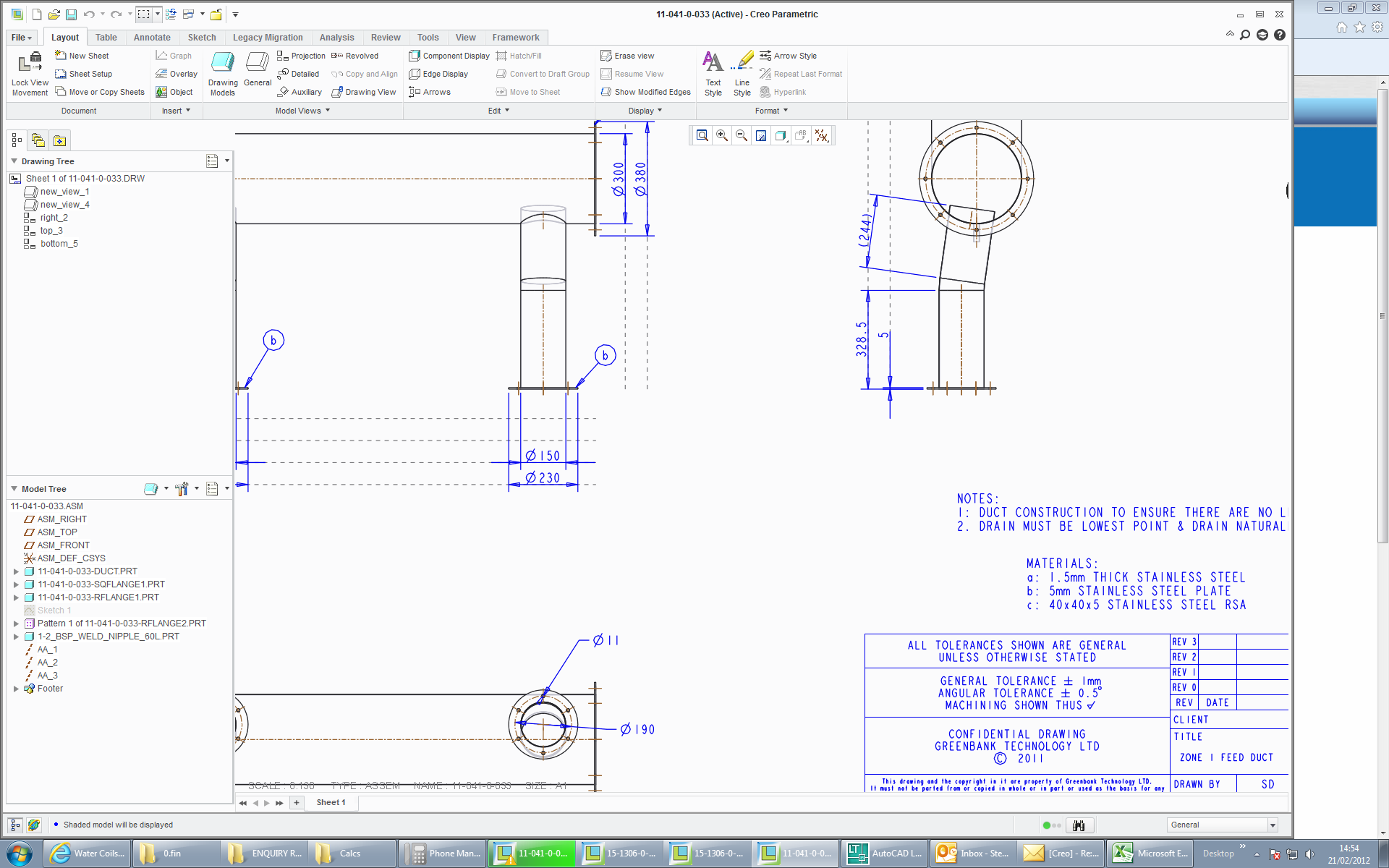
If you notice the dimensions at the bottom. I have a plain hole 11mm diameter and there are 6 around the pcd. I would like the note to say that fact. (I may at some point have 100 plain holes around the pcd therfore counting them isnt practical).
Also on the end view shown above and to the right I would like to dimension from the centre axis of each piece. I cannot select an centre line to dimension to.
- Mark as New
- Bookmark
- Subscribe
- Mute
- Subscribe to RSS Feed
- Permalink
- Notify Moderator
For showing the number of patterned instances, see item 3 in my previous reply.
I cannot think of why you would not be able to select a centerline. I've never had to change the config file to allow the selection of centerlines. Is it that you cannot select a centerline when placing dimensions or is it that you cannot select them at any time?
- Mark as New
- Bookmark
- Subscribe
- Mute
- Subscribe to RSS Feed
- Permalink
- Notify Moderator
Only that I cannot select them to dimension to.
I can highlight them and click them etc in any other mode.
- Mark as New
- Bookmark
- Subscribe
- Mute
- Subscribe to RSS Feed
- Permalink
- Notify Moderator
Is your dimension attachment type set to entity? If it is then, for now, I cannot think what is causing the problem.
I would try recreating the centerlines if they were created in an older version of Pro/E.
In case its needed, see this thread for making centerlines: http://communities.ptc.com/message/176624#176624
- Mark as New
- Bookmark
- Subscribe
- Mute
- Subscribe to RSS Feed
- Permalink
- Notify Moderator
Kevin.
Thanks very much for the help. You appear to have inadvertantly answered my question with your link to adding centrelines. My centrelines or axis show up in the drawing (more as ghosts then actual usable datums) but do not allow me to dimension to them until I have followed the method in the link.
Thanks again.
- Mark as New
- Bookmark
- Subscribe
- Mute
- Subscribe to RSS Feed
- Permalink
- Notify Moderator
Hi Kevin
Further to your answer yesterday about hole quantities I have come up with another question. I found that you can also report a hole quantity with and &p17 function or similar. This work well for holes patterned around and axis however with holes patterned with 2 directions you get 2 & figures. E.g. 3 holes vertical and 6 horizontal. I have also turned some of the hole instances off so instead of a 3x6 pattern of holes I only have 14 holes around a square flange. I cannot find a single & figure which displays the actual quantity of holes.
- Mark as New
- Bookmark
- Subscribe
- Mute
- Subscribe to RSS Feed
- Permalink
- Notify Moderator
I don't know how you used that &p17 function you mentioned, it did not work for me.
I don't thik it will be necessary, though. As we discussed earlier, the automatic hole note gives you the number of holes in the note. It will give you the number of holes if you create an axis pattern or a 2 dimension pattern. Then the note can be modified to match you drafting prefernces.
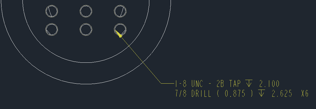
This is the default note. Notice the - ( 6 ) at the end. I created a pattern that has 3 holes in one direction and 2 holes in the other.

I modified the - ( 6 ) to show X6. You could move it the beginning of the note as 6X if needed.

Reminder: to edit the note, select it, right-click, pick edit value
- Mark as New
- Bookmark
- Subscribe
- Mute
- Subscribe to RSS Feed
- Permalink
- Notify Moderator
The hole note option only becomes available once I choose to have a tapped hole. If I just have a plain hole then I do not get the option for a hole note and therefore no quantity.
- Mark as New
- Bookmark
- Subscribe
- Mute
- Subscribe to RSS Feed
- Permalink
- Notify Moderator
There is something different about the methods that we are using.
I changed the hole type to exclude the tapping (circled in red).
The note updated as expected. The tap portion of the note was removed.

Then, I deleted the note to see if Show Model Annotations would bring it back and it did.
Read the thread again and see if something doesn't make sense.


