Community Tip - When posting, your subject should be specific and summarize your question. Here are some additional tips on asking a great question. X
- Community
- Creo+ and Creo Parametric
- 3D Part & Assembly Design
- Closing sweeps ends
- Subscribe to RSS Feed
- Mark Topic as New
- Mark Topic as Read
- Float this Topic for Current User
- Bookmark
- Subscribe
- Mute
- Printer Friendly Page
Closing sweeps ends
- Mark as New
- Bookmark
- Subscribe
- Mute
- Subscribe to RSS Feed
- Permalink
- Notify Moderator
Closing sweeps ends
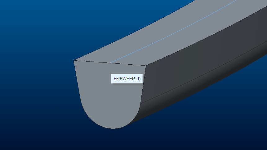
Recently, in my work I have to do a lot of sweeps, like the one bellow:

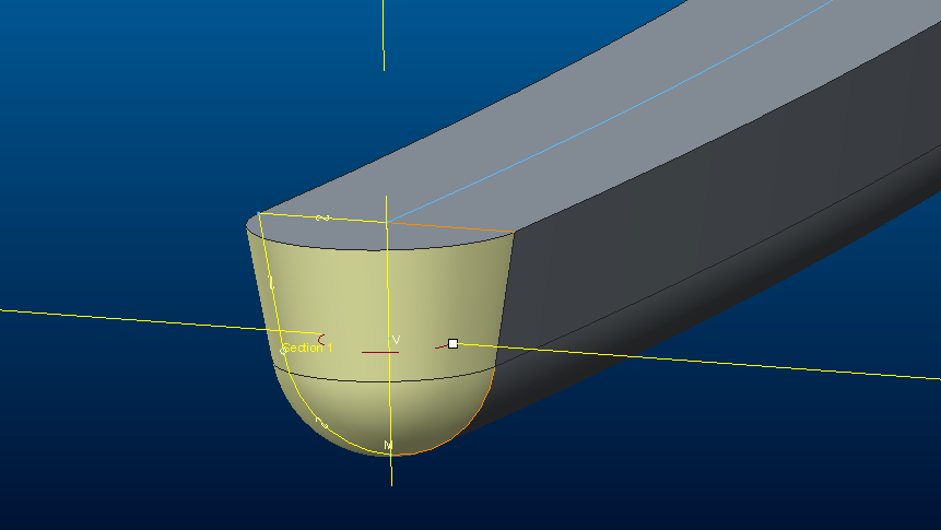
Now, to close the ends I have to do a revolve:

This doesn´t seem much work, but, to do the revolve it takes about 23 clicks (Revolve, Select Plane for skecth, add references, define axis, project, trim...) for each end. Total of 46 clicks for closing both sides.
I´m trying to figure out a easier way to do this. I tried copy/paste and udf´s , but both fail often.
Jose
This thread is inactive and closed by the PTC Community Management Team. If you would like to provide a reply and re-open this thread, please notify the moderator and reference the thread. You may also use "Start a topic" button to ask a new question. Please be sure to include what version of the PTC product you are using so another community member knowledgeable about your version may be able to assist.
Solved! Go to Solution.
Accepted Solutions
- Mark as New
- Bookmark
- Subscribe
- Mute
- Subscribe to RSS Feed
- Permalink
- Notify Moderator
Ok, I found a solution, maybe can be shortened a little but it´s the best I´ve got for now:
1 - Do the sweep
2 - Copy one end surface
3 - Trim it by half (by plane)
4 - Copy all edges of this surface
5 - Create a revolve using this edges
6 - Repeat in the other end.
Grouping it all together I just have to give 4 references for each runner: a curve, one end, other end and a normal plane.
I reduced from about 50 clicks to 5 or 6. Good enough for me.
- Mark as New
- Bookmark
- Subscribe
- Mute
- Subscribe to RSS Feed
- Permalink
- Notify Moderator
If you don't mind a small pip, a round does pretty well.
...and it can be C2 continuous.
- Mark as New
- Bookmark
- Subscribe
- Mute
- Subscribe to RSS Feed
- Permalink
- Notify Moderator
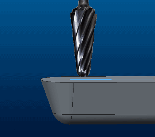
Since this is a channel to be milled, I have to keep the profile (angle and radius):

Nice pic, Huh??![]()
- Mark as New
- Bookmark
- Subscribe
- Mute
- Subscribe to RSS Feed
- Permalink
- Notify Moderator
I got to this within a few hundred... maybe a 1,000 clicks ![]()
Only few hundred more clicks might have achieved round'r ends.
I'm proud of it though... fully bound with curvature contraints!
Of course, you could sweep the 1/2 profile around the periphery .
- Mark as New
- Bookmark
- Subscribe
- Mute
- Subscribe to RSS Feed
- Permalink
- Notify Moderator
Excellent idea! ![]() 1 feature, nice!
1 feature, nice!
- Mark as New
- Bookmark
- Subscribe
- Mute
- Subscribe to RSS Feed
- Permalink
- Notify Moderator
Hah! You know me too well bro! I tried a VSS, figuring it would fail because the section became normal to the spine...and it did. Would be cool if it'd worked...... ![]() BUT...the full round is a more powerful tool than people think, it didn't work in this case (for some odd reason, maybe because the end surfs are angled), but if you add a radius to the end lines (ends normal to the sweep), then do a full round, you'd be surprised at how well that works.
BUT...the full round is a more powerful tool than people think, it didn't work in this case (for some odd reason, maybe because the end surfs are angled), but if you add a radius to the end lines (ends normal to the sweep), then do a full round, you'd be surprised at how well that works. ![]()
- Mark as New
- Bookmark
- Subscribe
- Mute
- Subscribe to RSS Feed
- Permalink
- Notify Moderator
You´re right, It can be done that way, but it´s much more complex to draw the boundaries instead of the centerlines. It´s a solution that I can´t use.
- Mark as New
- Bookmark
- Subscribe
- Mute
- Subscribe to RSS Feed
- Permalink
- Notify Moderator
You do not have the mold design package I am guessing?
- Mark as New
- Bookmark
- Subscribe
- Mute
- Subscribe to RSS Feed
- Permalink
- Notify Moderator
Yes I have, I can create runners with it, but...... the runner only allows to create cuts, not create "extrudes", I need to create the solid of the runners first, and then make a cut-out.
Also the runner feature seems to have some bugs.
- Mark as New
- Bookmark
- Subscribe
- Mute
- Subscribe to RSS Feed
- Permalink
- Notify Moderator
Ahhh, runners. Remember when you got a plastic model to put together, and there was more total material in the runners than the parts? ![]()
- Mark as New
- Bookmark
- Subscribe
- Mute
- Subscribe to RSS Feed
- Permalink
- Notify Moderator
Ok, can you do it backwards? create the channels first and then copy the surfaces to create your extrude version?
And not sure what bugs you have with runner tool, it seems to be one of the few that work really well in the mold package for me.
- Mark as New
- Bookmark
- Subscribe
- Mute
- Subscribe to RSS Feed
- Permalink
- Notify Moderator
...or All-in-One
- Mark as New
- Bookmark
- Subscribe
- Mute
- Subscribe to RSS Feed
- Permalink
- Notify Moderator
I may be off topic a little here, but thought this was worth a mention. I create a lot of channels cut into solid blocks, very similar in profile to Jose's. I had the same problem, how to round off the ends, to actually reproduce what a milling cutter would give. My approach is to use the hole feature, specifically 'hole on point placement'. Within the hole feature, you have the option to sketch a hole, sketch 'half' the profile in the same way you would, if doing a revolve end. I have placed datum points at each end of my sweep curve (geometry points added to the curve itself, cuts down on model tree features), select one for hole placement, & voila! you have a rounded end. What brings this into its own, is if you have multiple ends to do, you just copy & paste, selecting a new datum point for another end. Hopefully, the attached model & image explain my approach further.
Regards
John
- Mark as New
- Bookmark
- Subscribe
- Mute
- Subscribe to RSS Feed
- Permalink
- Notify Moderator
I was looking for that sketched hole in Creo 2 but didn't see at at a glance. Hope it is still there somewhere.
edit: phew.... yep, still there ![]()
- Mark as New
- Bookmark
- Subscribe
- Mute
- Subscribe to RSS Feed
- Permalink
- Notify Moderator
Nice, that´s something that I didn´t try. It´s a much more easy way to get it done.
But I see 2 disadvantages there:
1 - Dimensions of the hole aren´t constrained with the dimensions of the sweep. If you need to adjust values, you need to do it in three features.
2 - It´s only possible to remove material, not to add.
But a good option, no doubt about that.
Thanks
Jose
- Mark as New
- Bookmark
- Subscribe
- Mute
- Subscribe to RSS Feed
- Permalink
- Notify Moderator
Hi, with regards to point 1, you could link the hole dimensions to the sweep dimensions by relation, thats what i do.
John
- Mark as New
- Bookmark
- Subscribe
- Mute
- Subscribe to RSS Feed
- Permalink
- Notify Moderator
Ok, I found a solution, maybe can be shortened a little but it´s the best I´ve got for now:
1 - Do the sweep
2 - Copy one end surface
3 - Trim it by half (by plane)
4 - Copy all edges of this surface
5 - Create a revolve using this edges
6 - Repeat in the other end.
Grouping it all together I just have to give 4 references for each runner: a curve, one end, other end and a normal plane.
I reduced from about 50 clicks to 5 or 6. Good enough for me.
- Mark as New
- Bookmark
- Subscribe
- Mute
- Subscribe to RSS Feed
- Permalink
- Notify Moderator
That was my initial method as well, Jose, but I ended up with 23 clicks on each half. Since you mentioned 22 clicks per half, I assumed you used the same method. However, that copy/paste thing is nice ![]()
- Mark as New
- Bookmark
- Subscribe
- Mute
- Subscribe to RSS Feed
- Permalink
- Notify Moderator
Sorry if I wasn´t clear enough. My target is to replicate sweep and revolved ends with minimum number of clicks/references. Ideally, creating a UDF that only asks for a curve and a plane.
I started with the sweep and then creating a revolve at the ends. But to do the revolve, I can use only half of the section, projecting the edges, creating a line in the middle and trimming the curves.
No problem until this point.
Now I try copy/paste to the other end, it asks me all the edges references, and it fails often. I do the revolve manually again, group all features and try to copy/paste using other curve, problems....
I try to copy revolved ends to other sweeps with varied dimensions, problems...
The trick here was to copy the surface, trim it by half, and use all edges for the revolve.
Now I can replicate the sweep with revolved ends just giving a curve, a plane and two endpoints.
I have parts where I have to make twenty or thirty sweeps like these, now I make them much more faster. ![]()
Jose
- Mark as New
- Bookmark
- Subscribe
- Mute
- Subscribe to RSS Feed
- Permalink
- Notify Moderator
What if you change the order and put the revolves in first, and reference the tangent edges in the sweep?


