Community Tip - You can subscribe to a forum, label or individual post and receive email notifications when someone posts a new topic or reply. Learn more! X
- Community
- Creo+ and Creo Parametric
- 3D Part & Assembly Design
- Re: Collecting Dimension Results from Simulation, ...
- Subscribe to RSS Feed
- Mark Topic as New
- Mark Topic as Read
- Float this Topic for Current User
- Bookmark
- Subscribe
- Mute
- Printer Friendly Page
Collecting Dimension Results from Simulation, with associated features
- Mark as New
- Bookmark
- Subscribe
- Mute
- Subscribe to RSS Feed
- Permalink
- Notify Moderator
Collecting Dimension Results from Simulation, with associated features
Hello all,
I am using Feasibility/Optimization to simulate a gage interacting with the surface of a part. The features we are gaging are taper thread holes, and they repeat on the part, but part geometry creates a different offset distance between the gage's point of contact and the gage line in the hole.
When I perform the simulation, I'm left with an offset dimension that represents the distance we need to use to set the gage value for part acceptance target. I'm looking for a way to extract these linear dimensions and the features at either end to create a table with columns: Gage No. XX, Feature Name YY, Offset Dimension Z.ZZZ.
Can anyone offer a suggestion for how to extract this data?
Thanks.
- Labels:
-
2D Drawing
- Mark as New
- Bookmark
- Subscribe
- Mute
- Subscribe to RSS Feed
- Permalink
- Notify Moderator
This is incredibly cumbersome, a lot of work, hopeless.
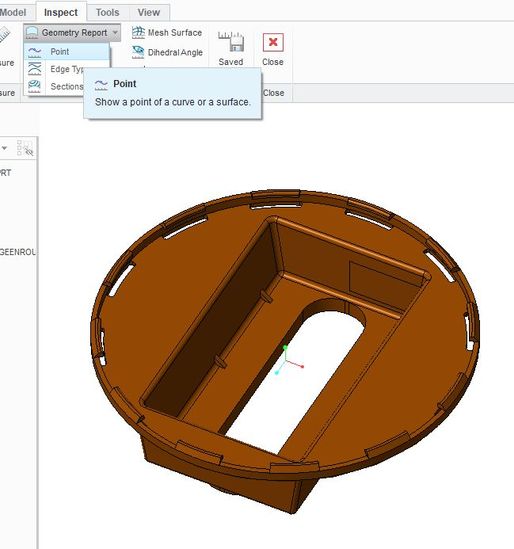
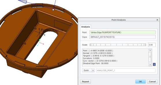
Look at the pictures, you can find point coordinates through Inspect-geometry report- point.
The top line, behind point gives x,y, z coordinates for tghe vertex you pick.
Good luck!
Regards
Erik


