Community Tip - Did you get called away in the middle of writing a post? Don't worry you can find your unfinished post later in the Drafts section of your profile page. X
- Community
- Creo+ and Creo Parametric
- 3D Part & Assembly Design
- Create projected 2D views of assemblies
- Subscribe to RSS Feed
- Mark Topic as New
- Mark Topic as Read
- Float this Topic for Current User
- Bookmark
- Subscribe
- Mute
- Printer Friendly Page
Create projected 2D views of assemblies
- Mark as New
- Bookmark
- Subscribe
- Mute
- Subscribe to RSS Feed
- Permalink
- Notify Moderator
Create projected 2D views of assemblies
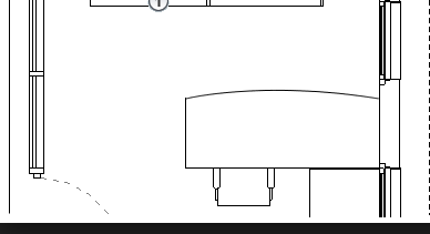
I'm working with colleagues who are using AutoCAD and one of their uses is to have building floor layouts with projected top-down views of the footprint of desks and equipment.
I have modelled a set of desks in Creo and need to figure out the easiest way of creating a DXF footprint.
Is there an automated way of doing this? For the moment, I can only think about creating a sketch on the floor plane referencing the outer edges of my assemblies but that's quite a time consuming process.
Thanks
This thread is inactive and closed by the PTC Community Management Team. If you would like to provide a reply and re-open this thread, please notify the moderator and reference the thread. You may also use "Start a topic" button to ask a new question. Please be sure to include what version of the PTC product you are using so another community member knowledgeable about your version may be able to assist.
Solved! Go to Solution.
- Labels:
-
2D Drawing
Accepted Solutions
- Mark as New
- Bookmark
- Subscribe
- Mute
- Subscribe to RSS Feed
- Permalink
- Notify Moderator
If you have already modeled your required plan then you can quickly create some top views in a drawing and save-as that drawing to .dxf or .dwg format that is AutoCAD format.
- Mark as New
- Bookmark
- Subscribe
- Mute
- Subscribe to RSS Feed
- Permalink
- Notify Moderator
If you have already modeled your required plan then you can quickly create some top views in a drawing and save-as that drawing to .dxf or .dwg format that is AutoCAD format.
- Mark as New
- Bookmark
- Subscribe
- Mute
- Subscribe to RSS Feed
- Permalink
- Notify Moderator
Just create a drawing from your Model by the following method,
New ---> Drawing (enable tic mark on the "Use Default template") ----> select "Use template" option -----> select the paper size -----> It will give you the default views of Front,Top & Side View
you can save as this file as DXF which can be opened in AutoCAD
- Mark as New
- Bookmark
- Subscribe
- Mute
- Subscribe to RSS Feed
- Permalink
- Notify Moderator
Thank you both for your responses, after playing around a bit, I went down the drawing route.
Once I changed the scale and removed the page border, it's fine and accurate. It just takes forever - need a more powerful PC - and creates a large file as it has all the details of every vertex.
Out of interest, is there a way of simplifying it further? I've already set the view to hide the hidden lines so simplified it as much as obviously possible.
Thanks ![]()
- Mark as New
- Bookmark
- Subscribe
- Mute
- Subscribe to RSS Feed
- Permalink
- Notify Moderator
Maybe your desk model is too detailed so your dxf output if too big. A desk can be as simple as a rectangle (4 lines).
A screen shot might help.

- Mark as New
- Bookmark
- Subscribe
- Mute
- Subscribe to RSS Feed
- Permalink
- Notify Moderator
It is quite complex and there are a lot of lines representing things on the desk. I could of course temporarily delete them / hide them so they don't show up. It would simplify the drawing. Or, once you have the DXF, manually delete the lines inside.


