

Creo Elements /Pro Routed Systems Designer drives Creo Elements /Direct Cabling
You can read the Desktop Product Focus of the Month here also authored by Jon Jarvis and you can also read the Enterprise Product Focus of the Month here and the Enterprise Tip of the Month here authored by Bruce Hulse.
| PTC Technical Specialists Newsletter - January 2011 |
Tip & Technique : Creo Elements /Pro Routed Systems Designer drives Creo Elements /Direct Cabling |
|---|
Creo Elements /Pro Routed Systems Designer (RSD) is a powerful 2D diagramming solution that enables the fast and easy creation of even the most sophisticated routed system diagrams. It has multi-discipline breadth, so it meets the functionality needs of piping as well as cabling design. Furthermore, RSD can automatically drive the routing of cables and pipes in virtually any 3D MCAD system that accepts the output format from RSD, and is specially optimized for use with the cabling and piping solutions within Creo Elements /Pro (formerly Pro/ENGINEER) and now Creo Elements /Direct Cabling (formerly CoCreate Cabling) 16.5 and higher.
With the recent announcement of Creo, we learned that PTC is focused on delivering products with value in 2D, 3D, and Bills or Materials/Assemblies. In the area of 2D there are two main areas of focus, 1) a simple 2D drafting tool and 2) 2D smart, rules-based schematic tool plus 2D drawings driven from 3D designs. As the key elements for Creo being PTC flagship products of Pro/ENGINEER, CoCreate, and ProductView, PTC is heavily investing in the integration of these tools to work in concert and drive real process value.
There are many advantages to RSD just as a standalone tool in its ability to:
1) build hierarchal schematics in a top-down, systems fashion,
2) have intelligent libraries with both graphical and parameter rich information,
3) simple easy tools to place components and interconnect those items quickly
4) generate smart, intelligent reporting on the design and 5) be able to optimize your electrical design using RSDSimulate Lite.
Additional benefit is gained when customers bridge the gap between electrical engineering tool (schematics) and mechanical engineering tool (CAD). This greatly improves communication between groups and improves the communication flow and change process by making sure both groups are working on the correct information as it relates to BOM’s, wire lists, net lists, and interconnect logical information. When the schematic & CAD tools are developed & integrated by a single source software company like PTC, it also guarantees a 1:1 correspondence in the electrical data as it flows back and forth between electrical engineering and mechanical engineering. For other vendors or programmers to integrate advanced tools like Routed Systems Designer with other CAD tools can be done, however, the quality checks and robustness will be at the mercy of the software integrator; not a simple task.
With the latest release of Creo Elements /Pro RSD 9.0, PTC now supports integration of logical interconnect information with the Creo Element /Direct Cabling 16.5 and higher. This is great news for existing CoCreate customers who did not have a schematic driven 3D cabling design in the past.
Here is how it works. RSD requires some additional parameters to be created in order to pass down the values for the designation of the connectors thru a *.con file, and the wire list/net list for the wires/cables thru a *.ecad file. See figure 1.
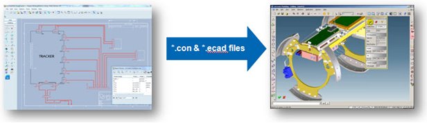
Figure 1: Schematic info passed to 3D design thru *.con file and *.ecad file
The required parameters for the designation of the connectors (*.con file) includes the following (See figure 2):
- Name – typically the reference designator name like –P10 – (i.e. Autogenerated from –P##)
- Package name – the corresponding CoCreate model name (i.e. MIL_0431_GRU)
- Do_not_export – set to false, used for criteria for exporting in reports
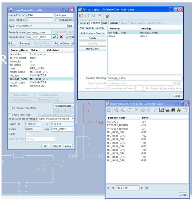
Figure 2: Required Connector Parameters and *.con report
The required parameters for the wire list/net list for wires & cables (*.ecad file) includes the following (See Figure 3):
- Name - for component, port, and fiber
- Package name – the corresponding CoCreate model name (i.e. MIL_0431_GRU)
- Wire_diameter – wire or cable thickness
- Color – wire color (i.e. RED, BLUE, etc)
- Do_not_export – set to false, used for criteria for exporting in reports
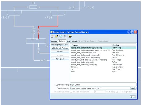
Figure 3: Required Wire list/Net list parameters and *.ecad report
Once the required parameters have been created and assigned proper values, you are ready to run the two key reports. The first report is set up to generate output for connector designation. Typically, you’ll need to set this report up once and save it to a file so it can be re-used. Open this report or create a new report. The report needs to have column tab set to show package name and name, and have the criteria tab set to “do_not_export” equal to “false”. If needed, a PTC RSD specialist has an example report “CoCreate-Connectors.rep” saved that can be sent to you with proper report settings for reference. See figure 4.
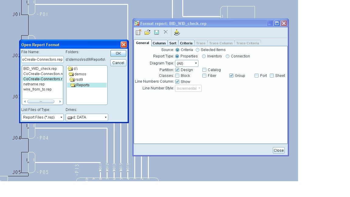
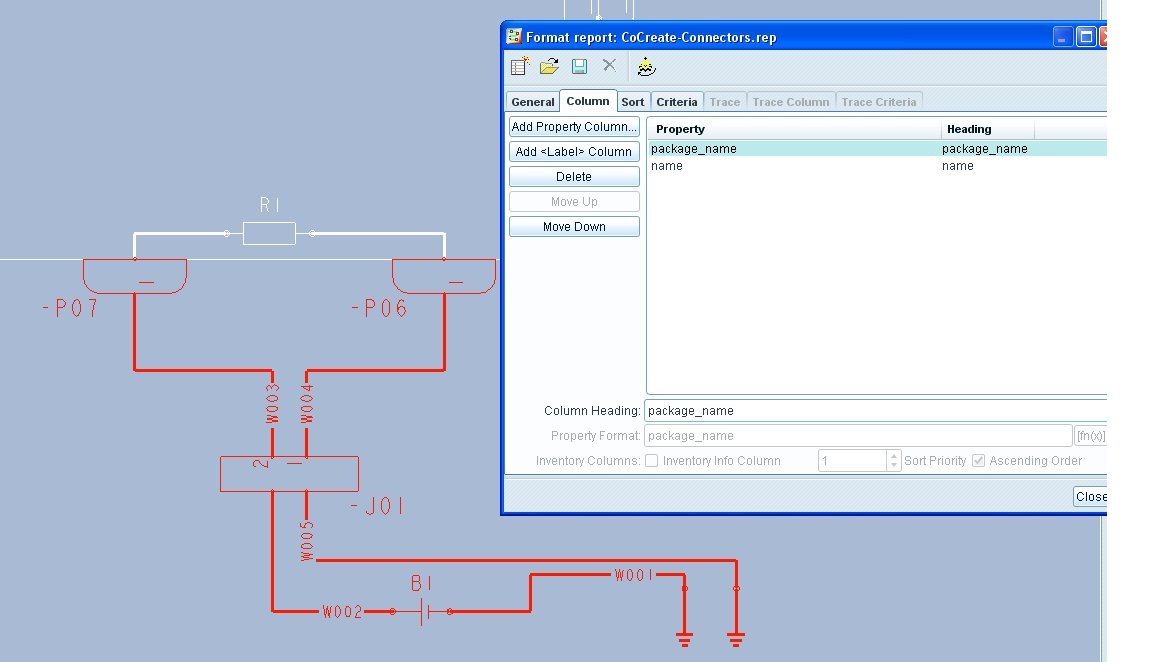
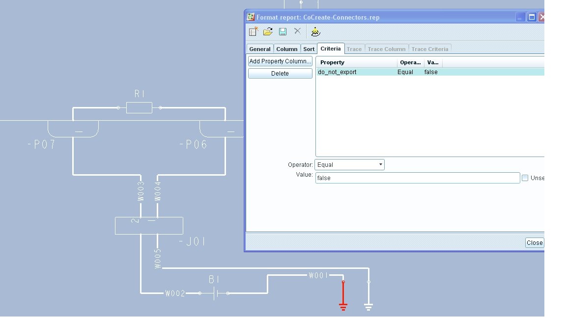
Figure 4: Setting Up Connector Report (*.con file)
Next, select the key connectors for your harness, and run the report. From the report results, select the save button in upper left corner, and save the report as a CoCreate connection (*.con file). This is one of two key final output files required for CoCreate. See Figure 5. Let’s look at the second output required now.
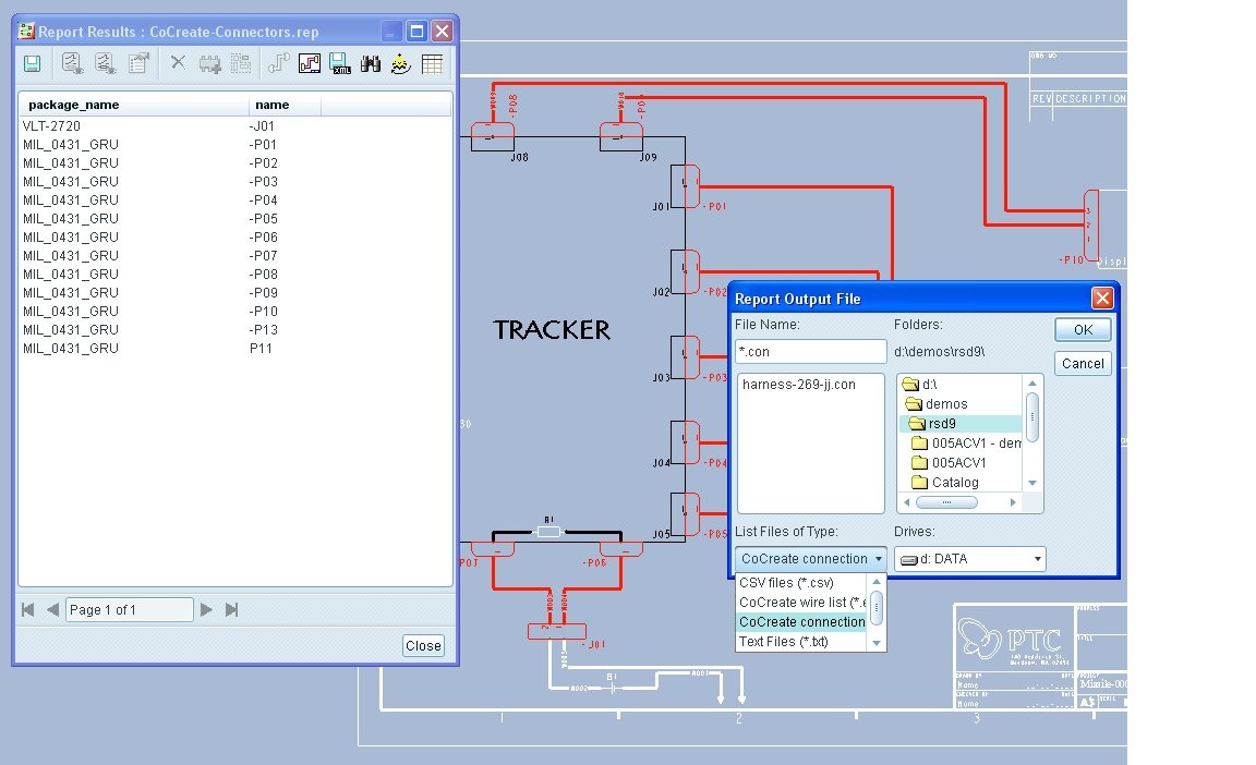
Figure 5: Save report as a *.con file for connector designation
The second report is set up to generate output for wire list/net list. Similarly to the first report, you’ll need to set this report up once and save it to a file so it can be re-used. Open this report or create a new report. The report needs to have column tab set to show from/to information as show in the figure 6 below. Also, the criteria tab set to “do_not_export” equal to “false. If needed, PTC RSD specialists have an example report “CoCreate-Connections.rep” saved that can be sent to you with proper report settings. See figure 6.
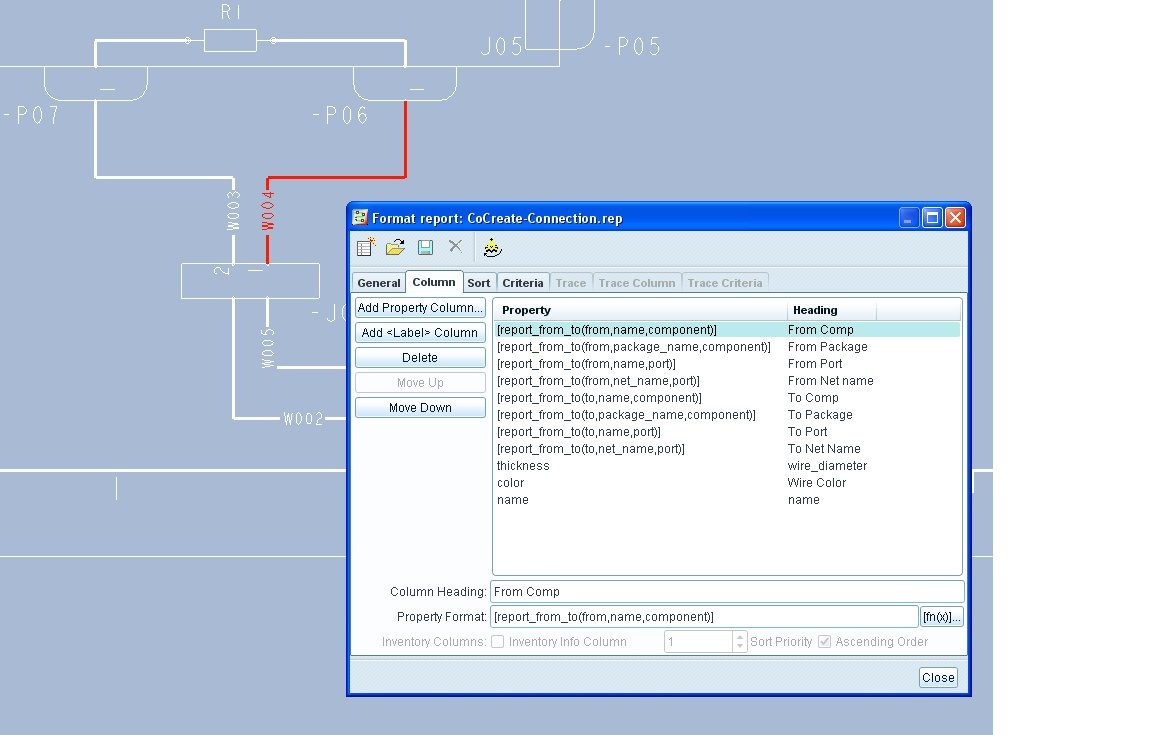
Figure 6: Setting Up Wire list/Net list Report (*.ecad file)
Next, select the key connectors, wires, cables for your harness, and run the report. From the report results, select the save button in upper left corner, and save the report as a CoCreate connection (*.ecad file). This is second output files required for CoCreate. See Figure 7.
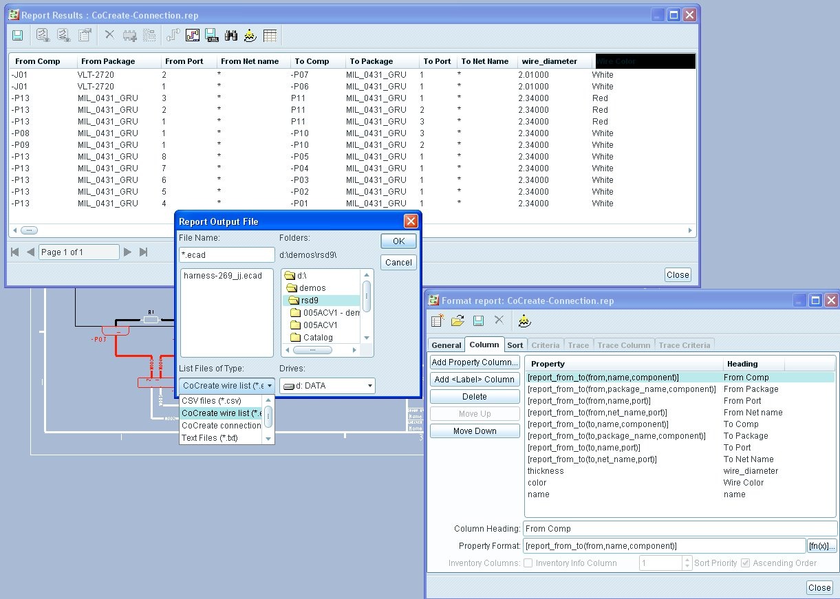
Figure 7: Save report as a *.ecad file for wire list/net list
Now that you have created your two key files, these files can be read into CoCreate to 1) designated the connectors, 2) route the wires and cables following the simple process below.
1) Open your design in Creo Elements /Direct Modeling Cabling.
2) Assemble the connectors in the proper location.
3) Designate the connectors by loading the *.con file created by RSD. The system will automatically match package name with 3D components.
4) Route the channels to define the key pathway for your harness.
5) Select the active harness to route your wires/cables.
6) Begin the auto routing of your connector by loading the *.ecad file for the wire list/net list. See Figure 8.
7) Verify that you have all the valid connectors designated.
😎 Go to the next tab – Valid, and connect all the valid connections of wires/cables. See Figure 9.
9) Now route the wires thru the channel using channel routing.
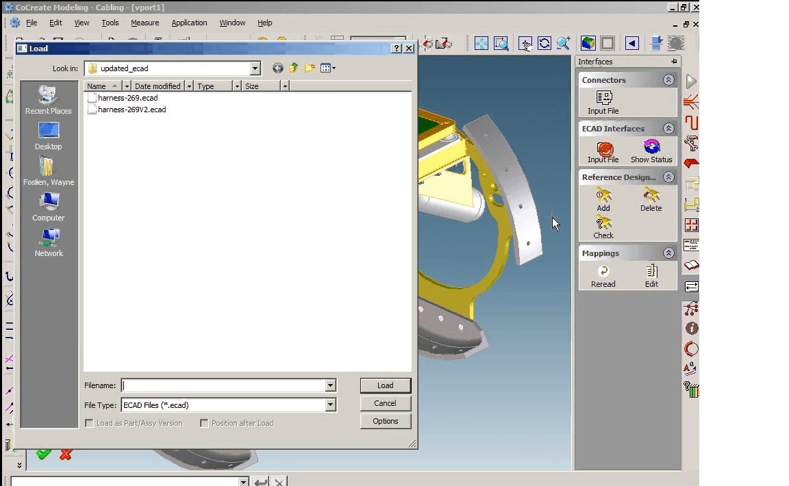
Figure 8: Reading input file *.ecad from RSD
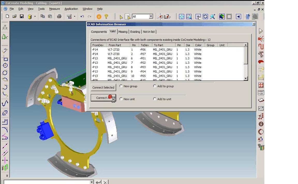
Figure 9: Auto routing all valid connections
You can learn a lot more about PTC Routed Systems solutions on our website. Visit the Routed Systems Home Page @ www.ptc.com/go/route . You can find out more info about 3D direct cabling here @ Creo Elements/Direct Cabling. Also, you can post a question on the Routed Systems Designer Independent Website www.rsdesigner.net . Lastly, here is a good demonstration on RSD: PTC - Creo Elements/Pro Routed Systems Designer Demo. Happy routing!
You can read the Desktop Product Focus of the Month here also authored by Jon Jarvis and you can also read the Enterprise Product Focus of the Month here and the Enterprise Tip of the Month here authored by Bruce Hulse.
This thread is inactive and closed by the PTC Community Management Team. If you would like to provide a reply and re-open this thread, please notify the moderator and reference the thread. You may also use "Start a topic" button to ask a new question. Please be sure to include what version of the PTC product you are using so another community member knowledgeable about your version may be able to assist.