Community Tip - Did you get an answer that solved your problem? Please mark it as an Accepted Solution so others with the same problem can find the answer easily. X
- Community
- Creo+ and Creo Parametric
- 3D Part & Assembly Design
- Diagonal stud at an odd angle
- Subscribe to RSS Feed
- Mark Topic as New
- Mark Topic as Read
- Float this Topic for Current User
- Bookmark
- Subscribe
- Mute
- Printer Friendly Page
Diagonal stud at an odd angle
- Mark as New
- Bookmark
- Subscribe
- Mute
- Subscribe to RSS Feed
- Permalink
- Notify Moderator
Diagonal stud at an odd angle
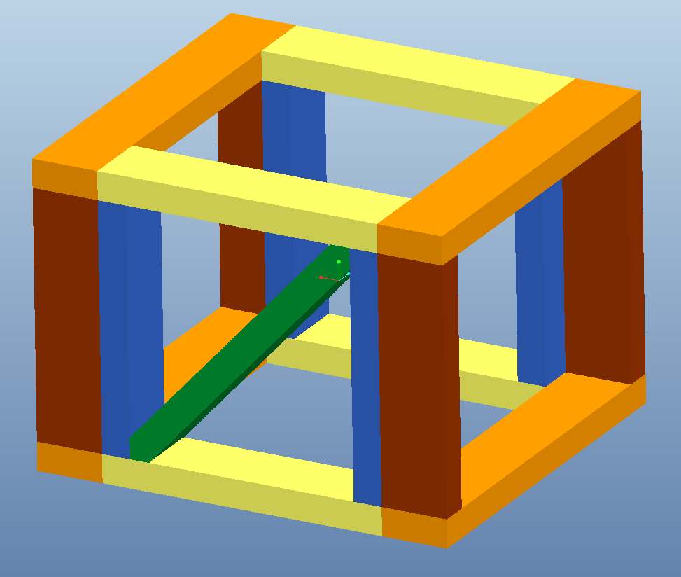
I've attached some shots of a problem I'm having. I have 2 vertical studs, with a horizontal member at the bottom and top. I'd like to put a diagonal stud in the opening that extends to the 2 sides/edges I've highlighted/pointed to in the 2nd and 3rd screencaptures. Now keep in mind this diagonal member will not be parallel to a plane through those 2 edges with the red arrows.... that's where my problem lies.
Originally I made a diagonal plane in the part that goes from one corner edge to the opposite corner edge (after an initial blind extrusion) and constrained that coincident to a diagonal plane in the assembly through the 2 edges I pointed to in the screencaps... but then when I change the extrusion to an 'Extrude To' (to those 2 planes I highlighted), it changed the angle of that diagonal plane which I used to constrain the diagonal member and in turn changed the location it needed to extrude to. It basically created a circular reference and would get closer and closer to being placed/extruded correctly.... but never would get there.
I realize I could just settle for it being really close, but i'm a perfectionist... and I'd like to know this process for the future if I have something that is detail oriented.
A little confusing, but I think I explained it properly.
Thanks in advance
This thread is inactive and closed by the PTC Community Management Team. If you would like to provide a reply and re-open this thread, please notify the moderator and reference the thread. You may also use "Start a topic" button to ask a new question. Please be sure to include what version of the PTC product you are using so another community member knowledgeable about your version may be able to assist.
- Labels:
-
Assembly Design
- Mark as New
- Bookmark
- Subscribe
- Mute
- Subscribe to RSS Feed
- Permalink
- Notify Moderator
Actually, I may be able to solve the problem if there is a way to reference dimensions from the assembly in a part file relation.... or drive a part file dimension with a relation in assembly mode. I don't know if this requires the Creo Advanced Assembly Extension, or if it may just be a function in relations that I'm not aware of.
- Mark as New
- Bookmark
- Subscribe
- Mute
- Subscribe to RSS Feed
- Permalink
- Notify Moderator
In a top-down modeling schema, you should be able to simply sketch a proper "interface" feature and align axes between the assembly and part or some level of reference like that. What I am getting at is that you should be able to use assembly references in the part model sketch if you create part features in the assembly.
Downside is that you will need to know all the pitfalls for top-down modeling techniques. Not so bad as long as the system can find all your parts (search path) and the assembly models are of a manageable size.
- Mark as New
- Bookmark
- Subscribe
- Mute
- Subscribe to RSS Feed
- Permalink
- Notify Moderator
Maybe this will illustrate my meaning... I used the "Create" in the assembly to start the new model which is a nice option for top-down modeling. Then activate the part to begin creating features. Sketcher references were picked from the assembly model (see points on corners for the centerline)
- Mark as New
- Bookmark
- Subscribe
- Mute
- Subscribe to RSS Feed
- Permalink
- Notify Moderator
Hi Chris...
Several answers come to mind. Have you thought about making the length of the diagonal beam a flexible feature? If you make that dimensions flexible, you can take a measurement at the assembly and use the result of that measurement to alter the beam length. This is great in that it doesn't make any crazy external references but your part will stay short until it's in the context of the assembly (which may not be what you want).
Here's a simple assembly I made in Wildfire 5 demonstrating the technique. Now that I think about it... maybe you need AAX for this because of the flex features. Ahh... I should've thought of that.
Anyway, if you modify the dimensions of the BOUNDING_BOX_SURF in the assembly and regenerate, everything will update. You can also alter the dimensions of the beams themselves. They were modeled as 2x4's (1.5" x 3.5") but you should be able to tweak that, too. I'm not 100% certain I included all the relations for tweaking the size of the beam but for certain you can modify the bounding box and all of the studs including the diagonal will automatically update.
This is a form of top-down design that's not used very often. A sketch or surface in the top level assembly drives the parts. I'd normally prefer to hide all the "guts" of the top down design in the skeleton part. I avoided a skeleton to demonstrate how the same technique can be used without an advanced license... of course then I used flexible features which may or may not be in AAX.
Write back if your license doesn't allow you to work with the model. Oh, and to answer your question- yes, assembly relations can modify part dimensions.

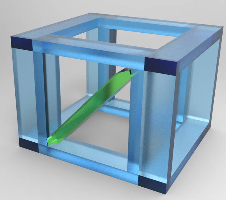
Or... just to show off... the same assembly made of frosted glass. Ignore the fact that the flexible feature didn't update before I rendered it. It's still pretty, isn't it?

Thanks!
-Brian


