Community Tip - Did you get called away in the middle of writing a post? Don't worry you can find your unfinished post later in the Drafts section of your profile page. X
- Community
- Creo+ and Creo Parametric
- 3D Part & Assembly Design
- Did You Know? Creating a Helical Pattern in PTC Cr...
- Subscribe to RSS Feed
- Mark Topic as New
- Mark Topic as Read
- Float this Topic for Current User
- Bookmark
- Subscribe
- Mute
- Printer Friendly Page
Did You Know? Creating a Helical Pattern in PTC Creo Parametric
- Mark as New
- Bookmark
- Subscribe
- Mute
- Subscribe to RSS Feed
- Permalink
- Notify Moderator
Did You Know? Creating a Helical Pattern in PTC Creo Parametric
Our weekly Did You Know series focuses on providing users with informative, “how-to” tips to help them get the most out of PTC Creo. This week’s post is based off an intermediate level tutorial which answers the question: “How do I create a helical pattern of a spherical cut on the side of a cylinder?” After reading this post, users we be able to complete this task in 3 steps.
Step 1: Create a Sketch Plane on the fly
The secret to making the helical pattern is in how the sketch plane is set up for the feature that you want to pattern. The dimensioning scheme for the sketch plane must support the pattern that you want to create.
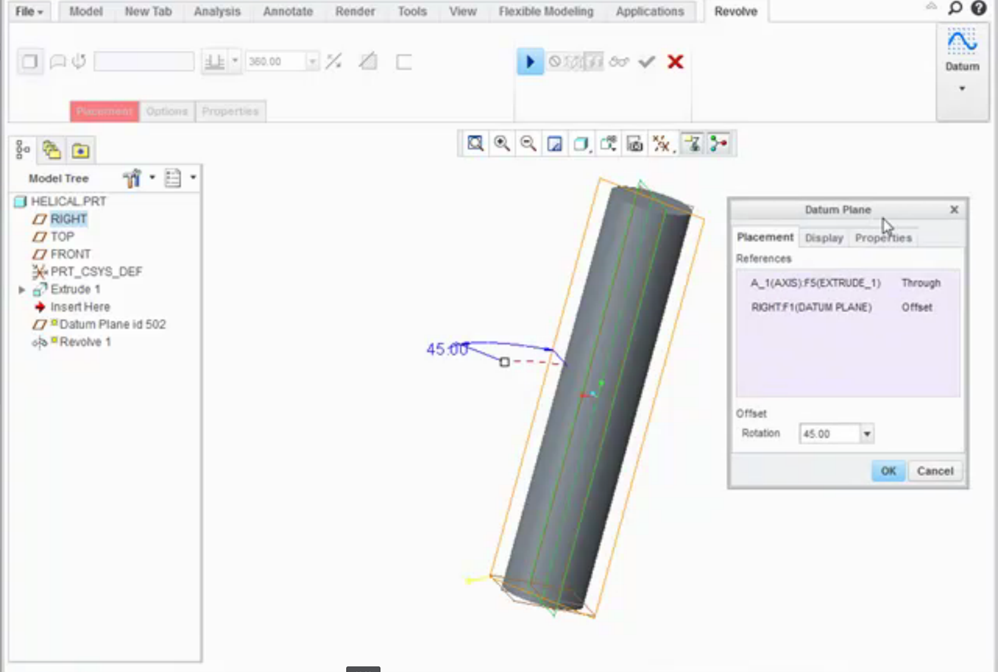
We will pattern a spherical cut which we will create with a Revolve feature. To begin, select Revolve and invoke the datum tool to create a datum plane on the fly.
Create the plane through the center axis of the cylinder and at an angle to one of the datum planes. The angular dimension will be used by the pattern as a dimension to increment when making subsequent instances, so the value here isn’t important, except for the placement of the first pattern instance. Accept the default value of 45 degrees.
 Creating the plane after invoking the datum tool
Step 2: Create the Revolved Cut
Resume the Revolve tool. The datum that you just created will be used as the sketch plane for the Revolve. In Sketcher, select References and capture the silhouette edge of the cylinder as a reference.
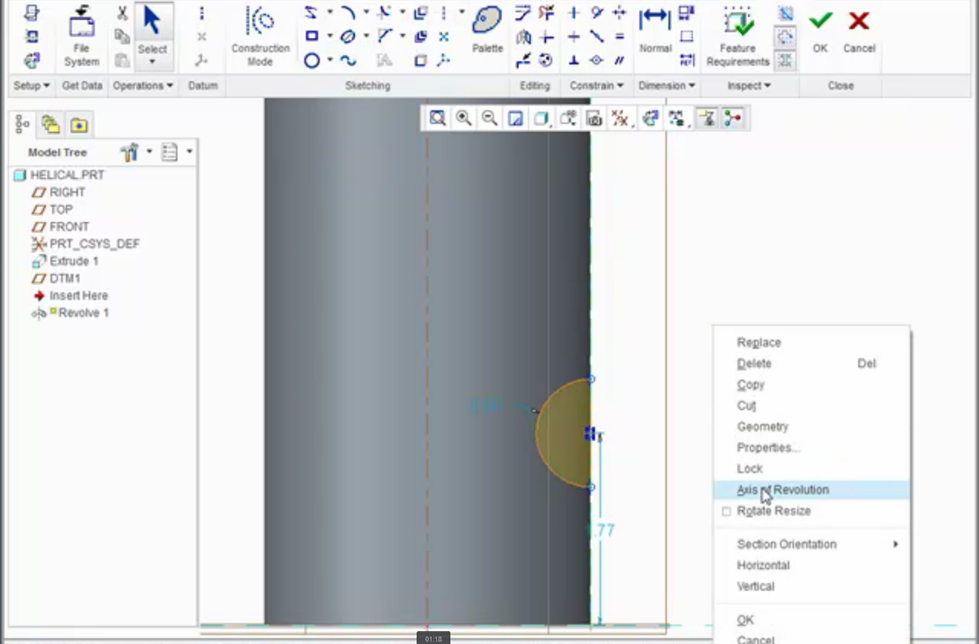
Next, using standard Sketcher workflows, create the half circle for the spherical cut at the edge of the cylinder. Create a Geometry Centerline along the edge of the cylinder for the half circle to revolve around. Designate this centerline as the Axis of Revolution.
Complete the Sketch, and select the option to Remove Material from the Revolve dashboard to make a cut.
 After creating the half circle, create a center line which will serve as the axis of revolution
Step 3: Create the helical pattern
After creating the first cut, you will have the dimensioning scheme needed to create the helical pattern. We will define the pattern to increment two dimensions in the same direction.
Select the Pattern tool for the revolve feature and open the Dimensions tab. Select the 45 degree dimension to rotate the feature around the shaft, and set the increment to 45 degrees. While holding the Control key, select the linear dimension from the end of the shaft to pattern the cut along the length of the shaft. Set the increment appropriately for the shaft size.
Finally, enter the number of instances you want to have in the pattern and complete the Pattern feature.
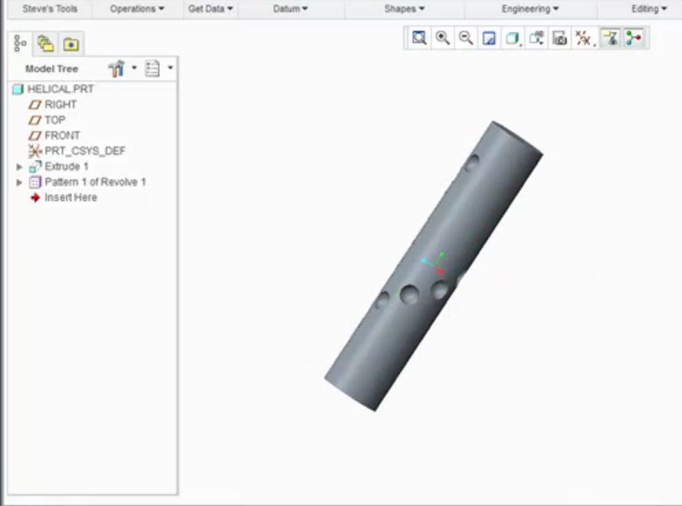
 The final product: a helical pattern on the side of a cylinder
PTC Creo Parametric gives you additional capabilities to define patterns. For example, the tutorial linked below demonstrates how to increase the number of revolved cuts that are patterned along the shaft by adding a second direction to the pattern.
In conclusion, creating a helical pattern on the side of a cylinder is simply a matter of setting up the sketch properly to get the correct dimensioning scheme and patterning two dimensions in the same direction.
Check out our video tutorial on the PTC University Learning Exchange (“Creating a Helical Pattern”) to see this advice in action. We’d also love to hear your suggestions for creating patterns in PTC Creo Parametric.
For more in-depth product feature explanations, visit our Tech Tips area.
Have some ideas about what PTC Creo product features you’d like to learn more about? Send me a message or leave a comment below and we’ll write up the best ideas from the community. Thanks for reading, looking forward to all of your feedback!
In case you missed it, here are our recent Did You Know posts:
1) Creating a Square to Round Blend
2) How to Create a Family Table
3) Tips and Tricks for Cable Design in PTC Creo Parametric Piping and Cabling Extension
This thread is inactive and closed by the PTC Community Management Team. If you would like to provide a reply and re-open this thread, please notify the moderator and reference the thread. You may also use "Start a topic" button to ask a new question. Please be sure to include what version of the PTC product you are using so another community member knowledgeable about your version may be able to assist.
- Labels:
-
General


