Community Tip - Visit the PTCooler (the community lounge) to get to know your fellow community members and check out some of Dale's Friday Humor posts! X
- Community
- Creo+ and Creo Parametric
- 3D Part & Assembly Design
- Did You Know? Using Flexible Move to Duplicate Sur...
- Subscribe to RSS Feed
- Mark Topic as New
- Mark Topic as Read
- Float this Topic for Current User
- Bookmark
- Subscribe
- Mute
- Printer Friendly Page
Did You Know? Using Flexible Move to Duplicate Surfaces
- Mark as New
- Bookmark
- Subscribe
- Mute
- Subscribe to RSS Feed
- Permalink
- Notify Moderator
Did You Know? Using Flexible Move to Duplicate Surfaces
Did you know you can easily duplicate the model’s surfaces and combine them with parting surfaces to form a mold component.
In this post, a PTC expert describes how to use the Move using Dragger function (available on the Flexible Modeling tab) to collect the surfaces and generate the reverse of the part.
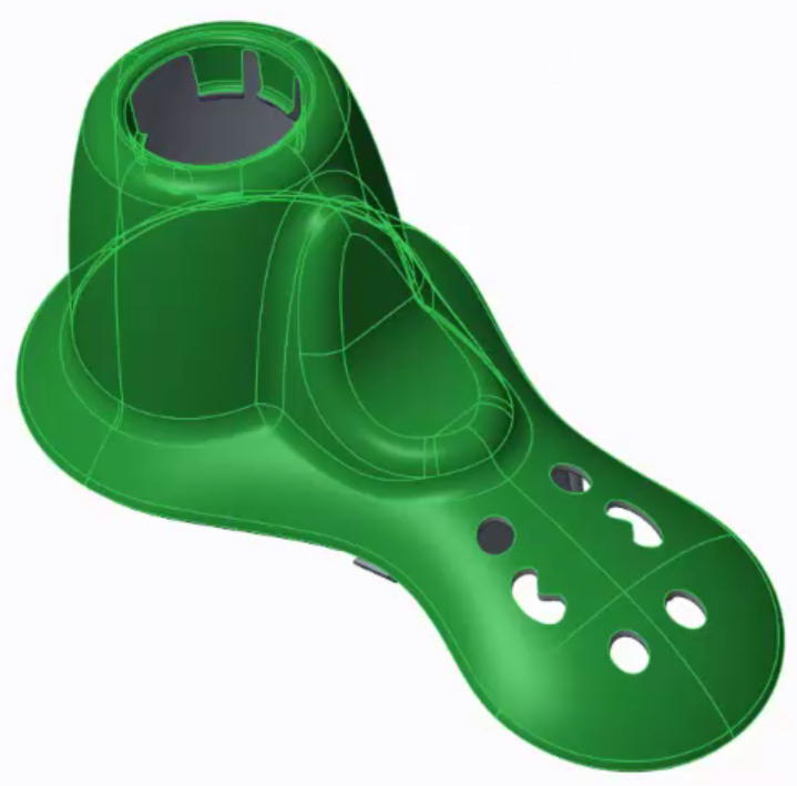
First, we will create a quilt surface on the reference part, and then that will be used in the mold assembly. To create the quilt surface, select a surface and then right-click and select the Tangent Surfaces option. This selects the outer surfaces of the model.

Image: The Tangent Surfaces option automatically causes the outer surfaces of the model to be selected.
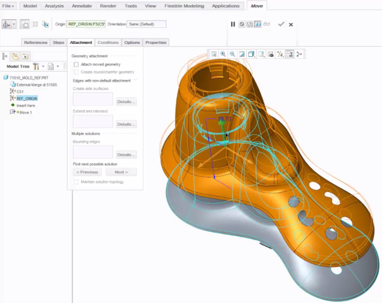
Next, to duplicate the selected surface using the Flexible Modeling > Move function. On the Attachment tab, clear Attach moved geometry. On the Move ribbon bar, click Origin Free (Default) and then select a reference coordinate system from the Model Tree.

Image: The 3D dragger (green arrow) can be used to move the duplicate surface.
On the Move ribbon bar, change the Tz (distance) value to zero (0.00). This ensures that the duplicate surface lies exactly on the model.
Then, on the Move ribbon bar, click the green check mark to apply and save the changes.
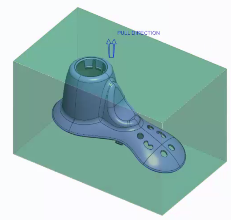
Now, the new surface can be used in a mold assembly, as shown below.

Image: The duplicate surface can be used easily in a mold assembly.
To watch a demonstration of these steps, check out our video tutorial (“Duplicating Surfaces Using Flexible Move”).
Stay tuned to our “Did You Know” blog series as we cover all of the exciting, new enhancements in PTC Creo 3.0.
Have some ideas about what PTC Creo product features you’d like to learn more about? Send me a message or leave a comment below and we’ll write up the best ideas from the community. Thanks for reading, looking forward to all of your feedback!
- Labels:
-
Reverse Engineering


