
Turn on suggestions
Auto-suggest helps you quickly narrow down your search results by suggesting possible matches as you type.
Showing results for
Please log in to access translation
Turn on suggestions
Auto-suggest helps you quickly narrow down your search results by suggesting possible matches as you type.
Showing results for
- Community
- Creo+ and Creo Parametric
- 3D Part & Assembly Design
- Re: Flexible component's constraints in assembly
Translate the entire conversation x
Please log in to access translation
Options
- Subscribe to RSS Feed
- Mark Topic as New
- Mark Topic as Read
- Float this Topic for Current User
- Bookmark
- Subscribe
- Mute
- Printer Friendly Page
Flexible component's constraints in assembly
Oct 14, 2025
06:52 AM
- Mark as New
- Bookmark
- Subscribe
- Mute
- Subscribe to RSS Feed
- Permalink
- Notify Moderator
Please log in to access translation
Oct 14, 2025
06:52 AM
Flexible component's constraints in assembly
Hello,
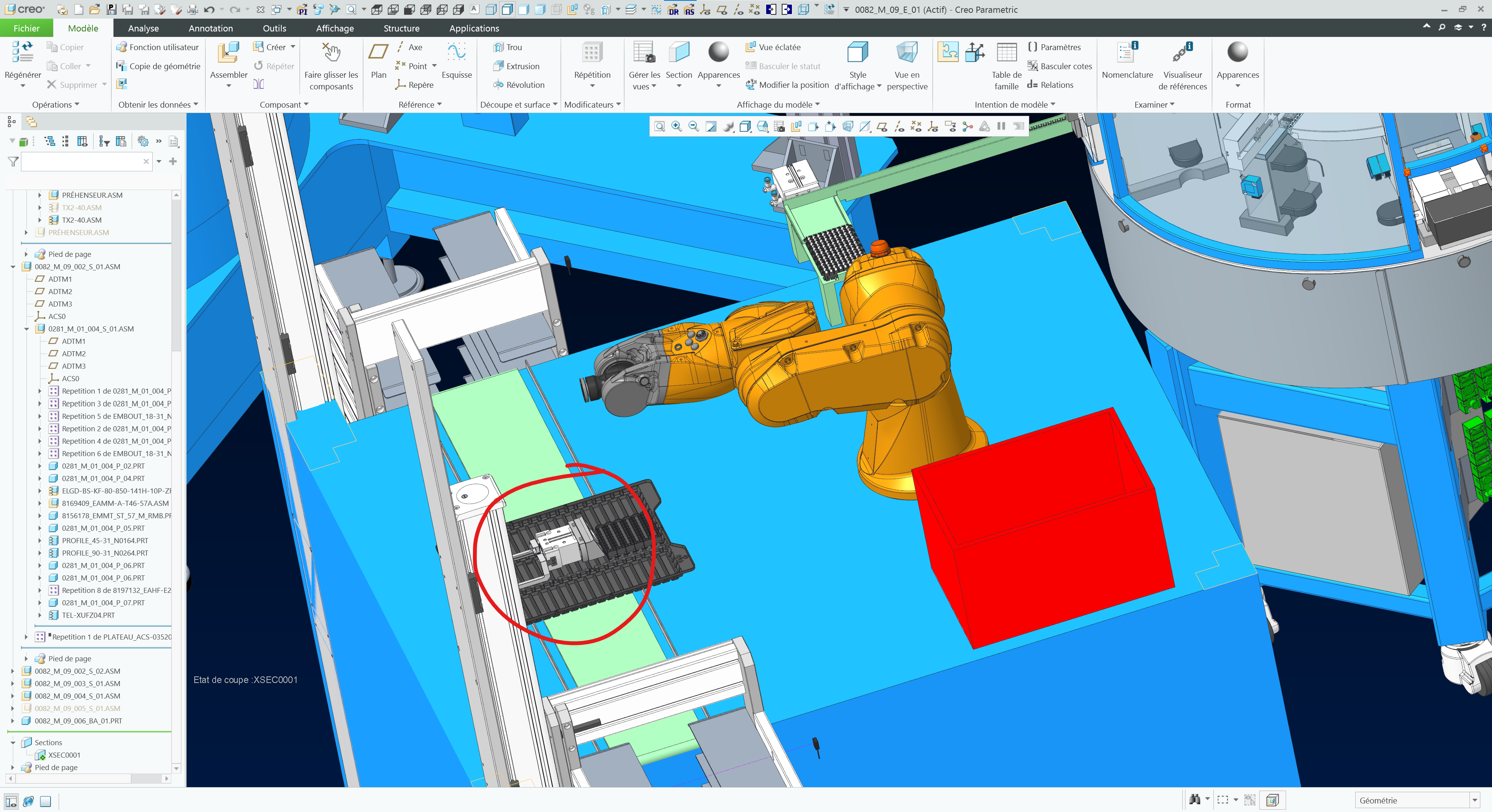
I'm asking help to know if there is a way in assembly to make constraint play on values of a flexible element. I have a 6DOF robot arm saved as an flexible asm. To place it I'm currently making his base's origin concurrent with the floor's one (cf. constraints.png).
In order to make it looks like the right position, I change each angle of rotation he had (which are all 6 flexible elements) degrees by degrees which is painfull (cf. flexible elements list.png).
Regarding this issue, I want to know if it's possible to add an other constraint on the robot arm, this time with gripper and make both of his constraints change the value of the flexible element instead of changing all by hand.
PS : I'm a using Creo 11
Labels:
2 REPLIES 2
Oct 14, 2025
11:25 AM
- Mark as New
- Bookmark
- Subscribe
- Mute
- Subscribe to RSS Feed
- Permalink
- Notify Moderator
Please log in to access translation
Oct 14, 2025
11:25 AM
That does not seem quite right way to use flexibility to model robots.
I'd treat the robot assembly as a mechanism and placed it into the parent assembly with a couple of rigid connections.
One constraining the base to the base coordinate system and one that constraints its gripper to the coordinate system that describes the gripper pose.
If the robot mechanism can achieve the gripper pose, then the joint angles needed will be figured out automatically...
Oct 14, 2025
12:25 PM
- Mark as New
- Bookmark
- Subscribe
- Mute
- Subscribe to RSS Feed
- Permalink
- Notify Moderator
Please log in to access translation
Oct 14, 2025
12:25 PM
I would agree with @pausob that your use of flexible components in the context of your model is not the best way to capture the design intent in Creo. Apply assembly constraints (or use the defined joints) to lock down the required DOFs in your model and set limit positions. You can use the drag model or explicitly position the gripper of the arm, and the kinematic chain will be correctly represented in the models.
| Joint Type   | Degrees of Freedom         | Description                                               |
|--------------|----------------------------|-----------------------------------------------------------|
| Rigid        | 0                          | No movement allowed; component is fixed in place.         |
| Pin          | 1 rotation                 | Allows rotation around a single axis (like a hinge).      |
| Slider       | 1 translation              | Allows linear motion along one axis.                      |
| Cylinder     | 1 rotation + 1 translation | Rotation and translation along the same axis.             |
| Planar       | 2 translation + 1 rotation | Movement in a plane and rotation about its normal axis.   |
| Ball         | 3 rotation                 | Full rotational freedom (like a ball-and-socket joint).   |
| Bearing      | 1 rotation                 | Rotation along a defined trajectory.                      |
| Weld         | 0                          | Fixed using coordinate system and offset; used in welds.  |
========================================
Involute Development, LLC
Consulting Engineers
Specialists in Creo Parametric
Involute Development, LLC
Consulting Engineers
Specialists in Creo Parametric


