
Turn on suggestions
Auto-suggest helps you quickly narrow down your search results by suggesting possible matches as you type.
Showing results for
Please log in to access translation
Turn on suggestions
Auto-suggest helps you quickly narrow down your search results by suggesting possible matches as you type.
Showing results for
Community Tip - Stay updated on what is happening on the PTC Community by subscribing to PTC Community Announcements. X
- Community
- Creo+ and Creo Parametric
- 3D Part & Assembly Design
- Inheritance tolerance display problem:(
Translate the entire conversation x
Please log in to access translation
Options
- Subscribe to RSS Feed
- Mark Topic as New
- Mark Topic as Read
- Float this Topic for Current User
- Bookmark
- Subscribe
- Mute
- Printer Friendly Page
Inheritance tolerance display problem:(
Oct 15, 2012
01:44 AM
- Mark as New
- Bookmark
- Subscribe
- Mute
- Subscribe to RSS Feed
- Permalink
- Notify Moderator
Please log in to access translation
Oct 15, 2012
01:44 AM
Inheritance tolerance display problem:(
Hi Guys,
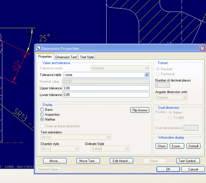
I am struck again, below shown image tells my problem i.e. I couldn't add tolerance to the dimension(22) that came from inheritance(Tolerance mode tab itself is greyed out), tried changing the tol_display option & no result. waiting for the solution guys:)
FYI.. the dimension is from core which is used in casting & below shown is the casting drawing, there is no seperate drawing for core i.e. core details also shown in this drawing only.
Cheers,
Hari
This thread is inactive and closed by the PTC Community Management Team. If you would like to provide a reply and re-open this thread, please notify the moderator and reference the thread. You may also use "Start a topic" button to ask a new question. Please be sure to include what version of the PTC product you are using so another community member knowledgeable about your version may be able to assist.
Solved! Go to Solution.
Labels:
- Labels:
-
2D Drawing
ACCEPTED SOLUTION
Accepted Solutions
Jun 25, 2013
06:49 PM
- Mark as New
- Bookmark
- Subscribe
- Mute
- Subscribe to RSS Feed
- Permalink
- Notify Moderator
Please log in to access translation
Jun 25, 2013
06:49 PM
Hello Hari,
Not sure if this will answer your question , just some info on Inheritance feature & tolerances :
1. When modifying Dim Properties of inheritance feature dimension, it is impossible to change Tolerance Mode. It is always the same as in base model. So if you have just "Nominal" type dim in core part, you will not be able to add any Tol on cavity it it uses core Inheritance cut. Same in 3D or in Drawing.
2. In general if you have some tolerance defined on base part dimension, its value can be easely modified on inheritance feature. Either through inheritance Varied Dimension table (show tolerances on the screen and pick one for Var Dims), or by direct edit/pick on TOL value on 3D screen. This should provide confirmation to add this TOL to varied items list and ytou should be able to proceed.
3. Do not try to use Properties dialogue to create/modify varied dimensions or tolerances - use direct selection of nominal / tolerances from the screen
4. When workingin show tolerances mode, you will not be able to make any modification to LIMITS type dimension of Inheritance feature - so hope you do not use LIMITS. Any other type (nominal, plus/minus, symmetrical) is available.
However if you switch off tolerances you can add any type of DIM to varied items of Inheritance feature ... since it handles all as nominal.
If this does not help feel free to ask more precise one.
12 REPLIES 12
Oct 15, 2012
03:04 AM
- Mark as New
- Bookmark
- Subscribe
- Mute
- Subscribe to RSS Feed
- Permalink
- Notify Moderator
Please log in to access translation
Oct 15, 2012
03:04 AM
Hi, Hari,
try to set different "tolerance mode", hope it is work for you.
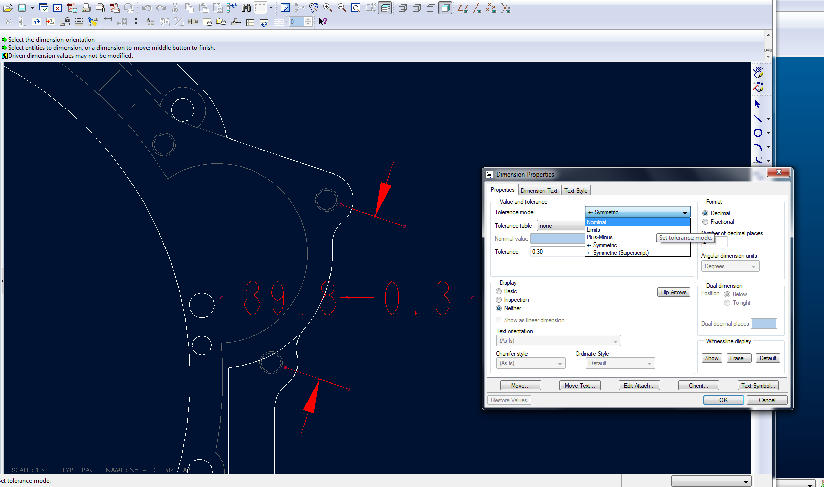
other wise, you need to modify configuration.in file>properties>drawing opetion, you can find a lot of setting. if above tolerance mode tring do not work, tell us, I find some possible setting optional for you.
Best regards, Hongjie
Oct 15, 2012
04:30 AM
- Mark as New
- Bookmark
- Subscribe
- Mute
- Subscribe to RSS Feed
- Permalink
- Notify Moderator
Please log in to access translation
Oct 15, 2012
04:30 AM
Hi Hongjie,
Thanks for you reply,
But the option "Tolerance mode" itself is greyed out, please let me know how to activate that option.
Cheers,
Hari
Oct 15, 2012
04:50 AM
- Mark as New
- Bookmark
- Subscribe
- Mute
- Subscribe to RSS Feed
- Permalink
- Notify Moderator
Please log in to access translation
Oct 15, 2012
04:50 AM
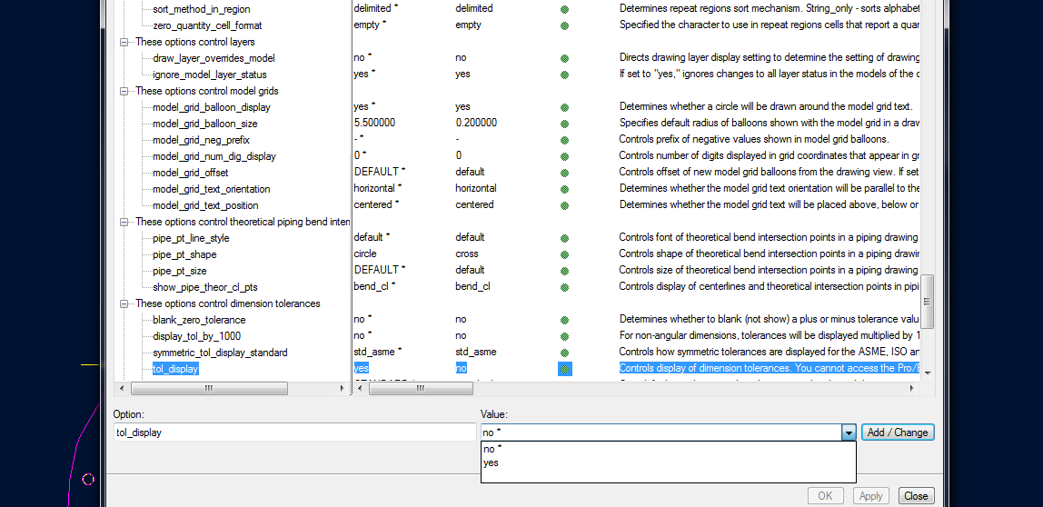
try to set optional: tol_display to yes.
I have just try it in my ProE WF4.0 and found "tolerance mode" grey out during "tol display' is setted in no.
for setting config, go to file>properties>drawing opetion
Best regards, Hongjie
Oct 15, 2012
04:57 AM
- Mark as New
- Bookmark
- Subscribe
- Mute
- Subscribe to RSS Feed
- Permalink
- Notify Moderator
Please log in to access translation
Oct 15, 2012
04:57 AM
That was the first option I tried but no luck:(
Oct 15, 2012
05:02 AM
- Mark as New
- Bookmark
- Subscribe
- Mute
- Subscribe to RSS Feed
- Permalink
- Notify Moderator
Please log in to access translation
Oct 15, 2012
05:02 AM
let us waiting for expert come.
-Hongjie
Oct 15, 2012
07:47 PM
- Mark as New
- Bookmark
- Subscribe
- Mute
- Subscribe to RSS Feed
- Permalink
- Notify Moderator
Please log in to access translation
Oct 15, 2012
07:47 PM
Can you change the tolerance mode in the Core Model rather than the drawing? Remember you can set the Tol_Display in the detail options and the config.pro options separately.
Oct 16, 2012
06:15 AM
- Mark as New
- Bookmark
- Subscribe
- Mute
- Subscribe to RSS Feed
- Permalink
- Notify Moderator
Please log in to access translation
Oct 16, 2012
06:15 AM
Hi Antonius,
Thanks for the reply buddy, I have already tried following options
1. Change the tol_display status in core model first, changed the properties of the dimension to call out unequal; tolerance that is required.
2. Updated inheritance in casting model.
3. Changed tol_display status in casting part.
4. Then went on to change drawing options.
no luck, is there any other ways please:(
Hari
Oct 16, 2012
11:01 AM
- Mark as New
- Bookmark
- Subscribe
- Mute
- Subscribe to RSS Feed
- Permalink
- Notify Moderator
Please log in to access translation
Oct 16, 2012
11:01 AM
I have not seen this but I have seen model corruption before that acts strangly on dimensions (old and new). Have you considered submitting the files to PTC support?
Oct 16, 2012
09:26 AM
- Mark as New
- Bookmark
- Subscribe
- Mute
- Subscribe to RSS Feed
- Permalink
- Notify Moderator
Please log in to access translation
Oct 16, 2012
09:26 AM
Harish,
I think you may be getting the .dtl file that comes with the inheritance. Have you tried loading and applying the .dtl file that your company uses? In WF5 this can be accessed from File, Drawing Model. You could also edit the existing .dtl file with the following: tol_display YES.
Hope this helps,
Tim
Jun 24, 2013
04:21 PM
- Mark as New
- Bookmark
- Subscribe
- Mute
- Subscribe to RSS Feed
- Permalink
- Notify Moderator
Please log in to access translation
Jun 24, 2013
04:21 PM
Was there ever a solution to this? I've seen many SPRs related to tolerances and inheritance features. In my case the base part is released and read only. You can vary a dimention in the child model but changing the tolerance is greyed out in part and drawing mode.
Jun 24, 2013
06:05 PM
- Mark as New
- Bookmark
- Subscribe
- Mute
- Subscribe to RSS Feed
- Permalink
- Notify Moderator
Please log in to access translation
Jun 24, 2013
06:05 PM
I have noticed that when I bring drawings up in Creo the tolerance mode is greyed out. What I have found is that if I go to File, Prepare, Drawing Properties, then click the change in the Detail Options, it brings up a file in which the tolerance display is set to no. After I change that setting to yes, the tolerance is no longer greyed out. I don't know the reason for this, as my config.pro and my .dtl file both have the tolerance display set to yes, and the tolerance mode to plusminussym. I haven't played with Creo that much so I haven't been able to make it work correctly from the start.
Jun 25, 2013
06:49 PM
- Mark as New
- Bookmark
- Subscribe
- Mute
- Subscribe to RSS Feed
- Permalink
- Notify Moderator
Please log in to access translation
Jun 25, 2013
06:49 PM
Hello Hari,
Not sure if this will answer your question , just some info on Inheritance feature & tolerances :
1. When modifying Dim Properties of inheritance feature dimension, it is impossible to change Tolerance Mode. It is always the same as in base model. So if you have just "Nominal" type dim in core part, you will not be able to add any Tol on cavity it it uses core Inheritance cut. Same in 3D or in Drawing.
2. In general if you have some tolerance defined on base part dimension, its value can be easely modified on inheritance feature. Either through inheritance Varied Dimension table (show tolerances on the screen and pick one for Var Dims), or by direct edit/pick on TOL value on 3D screen. This should provide confirmation to add this TOL to varied items list and ytou should be able to proceed.
3. Do not try to use Properties dialogue to create/modify varied dimensions or tolerances - use direct selection of nominal / tolerances from the screen
4. When workingin show tolerances mode, you will not be able to make any modification to LIMITS type dimension of Inheritance feature - so hope you do not use LIMITS. Any other type (nominal, plus/minus, symmetrical) is available.
However if you switch off tolerances you can add any type of DIM to varied items of Inheritance feature ... since it handles all as nominal.
If this does not help feel free to ask more precise one.


