
Turn on suggestions
Auto-suggest helps you quickly narrow down your search results by suggesting possible matches as you type.
Showing results for
Please log in to access translation
Turn on suggestions
Auto-suggest helps you quickly narrow down your search results by suggesting possible matches as you type.
Showing results for
Community Tip - When posting, your subject should be specific and summarize your question. Here are some additional tips on asking a great question. X
- Community
- Creo+ and Creo Parametric
- 3D Part & Assembly Design
- Modify Drawing Dimensions (Creo 2)
Translate the entire conversation x
Please log in to access translation
Options
- Subscribe to RSS Feed
- Mark Topic as New
- Mark Topic as Read
- Float this Topic for Current User
- Bookmark
- Subscribe
- Mute
- Printer Friendly Page
Modify Drawing Dimensions (Creo 2)
May 24, 2013
10:42 AM
- Mark as New
- Bookmark
- Subscribe
- Mute
- Subscribe to RSS Feed
- Permalink
- Notify Moderator
Please log in to access translation
May 24, 2013
10:42 AM
Modify Drawing Dimensions (Creo 2)
I have a few questions on how these dimensions were modified. Hopefully someone can help...
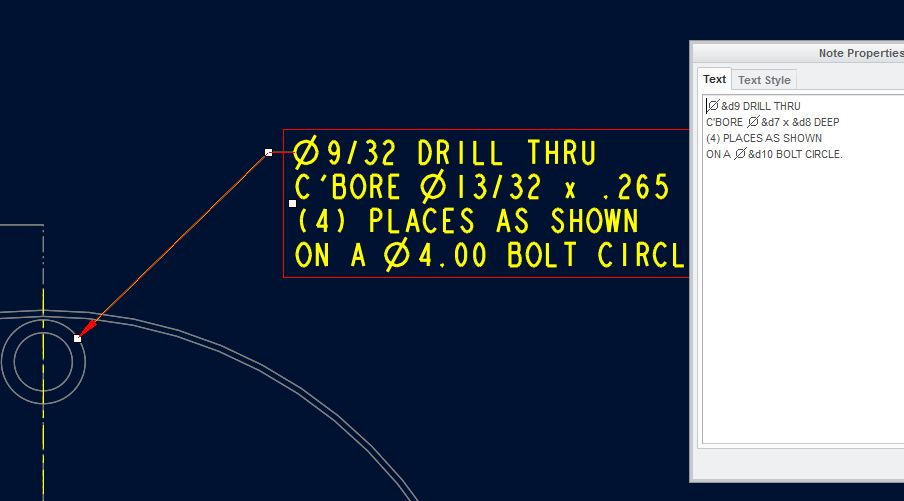
On the hole note, how do I find the feature numbers that were used?
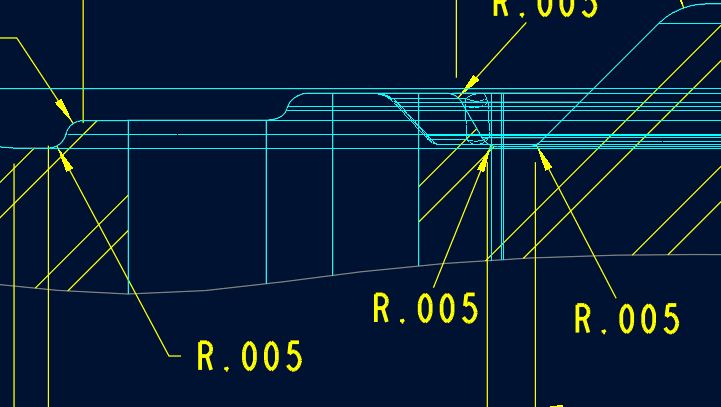
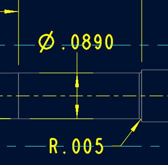
On the two pics below, how was the tail cut from the leader and the text reoriented?
Thank you kindly in advance,
Matt
This thread is inactive and closed by the PTC Community Management Team. If you would like to provide a reply and re-open this thread, please notify the moderator and reference the thread. You may also use "Start a topic" button to ask a new question. Please be sure to include what version of the PTC product you are using so another community member knowledgeable about your version may be able to assist.
Labels:
- Labels:
-
General
3 REPLIES 3
May 24, 2013
11:06 AM
- Mark as New
- Bookmark
- Subscribe
- Mute
- Subscribe to RSS Feed
- Permalink
- Notify Moderator
Please log in to access translation
May 24, 2013
11:06 AM
Part 2 of your question is easy; use the shift key to move just the text.
...for the 1st Q, what happens when you switch text for symbols?
May 24, 2013
11:49 AM
- Mark as New
- Bookmark
- Subscribe
- Mute
- Subscribe to RSS Feed
- Permalink
- Notify Moderator
Please log in to access translation
May 24, 2013
11:49 AM
Per Antonius discussion for the 1st Q. The &d9, &d7, &d8 and &d10 probably are the text names for the dimensions for the various holes, diameters and circles in the model. While in the model and you right click to edit the feature, goto Info->Switch Dimensions and the dimension will change from their numeric value to their text value. This should show you the &d## for the dimensions. Hope this helps. Dale
May 28, 2013
07:31 AM
- Mark as New
- Bookmark
- Subscribe
- Mute
- Subscribe to RSS Feed
- Permalink
- Notify Moderator
Please log in to access translation
May 28, 2013
07:31 AM
Both worked. Thanks!
Matt


