cancel
Showing results for 
Search instead for 
Did you mean: 
cancel
Showing results for 
Search instead for 
Did you mean: 

Community Tip - Did you get an answer that solved your problem? Please mark it as an Accepted Solution so others with the same problem can find the answer easily. X

Need help defining and using 45 degree face mill

nlehman
12-Amethyst

Need help defining and using 45 degree face mill

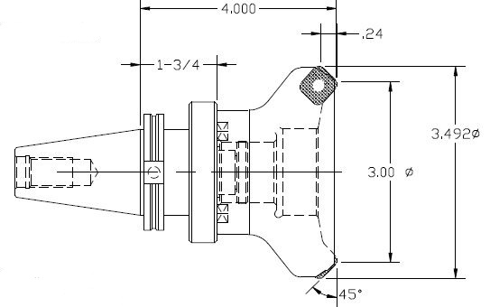
When trying to define a tool for face milling, I am unable to find a tool that gives the option of having an angle associated with it, radius seems to be the option.  45 degree face mills are a fairly common tool, how can I define this tool?  I am trying to face the part, and then mill the 45 degree angle in the part all with the same tool.  Aside of being unable to define the 45 degree face mill under face milling, I am also unable to use a face mill for chamfer milling.  The cam software that is being replaced does this job all with the same tool, and it is my job to replicate that.  What would be the easiest way to do this in Creo?


Here the part needs to be face milled, and then using the same 45 degree face mill needs to mill the highlighted 45 degree chamfer.
Capture.JPG

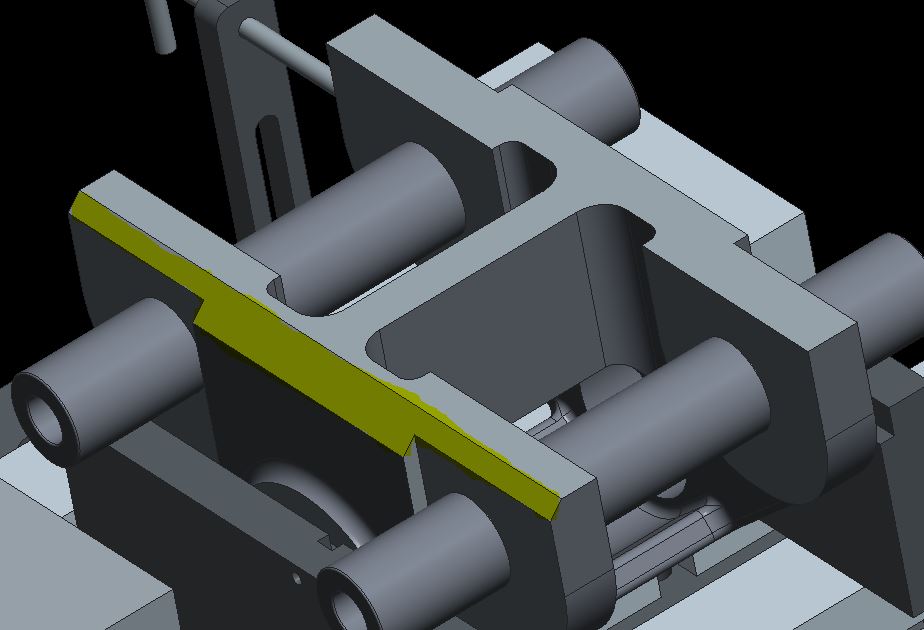
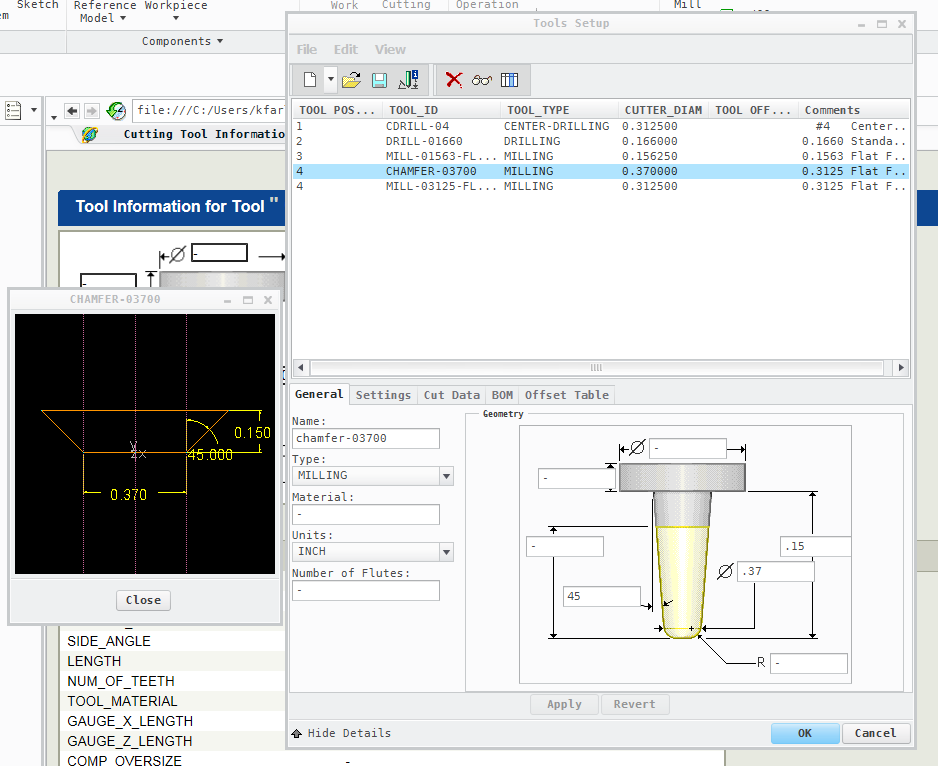
This is the tool I am using.

Capture1.JPG

1 ACCEPTED SOLUTION

Accepted Solutions
KenFarley
21-Topaz I
(To:nlehman)

I will probably be chastised for doing so, but I never use the specific "chamfer" toolpaths. If I need a chamfer I usually use a trajectory milling path. Unless the desired chamfer is on a non-planar surface, then I resort to surface milling with a ball end mill.

To define a tool for chamfering, I just use a standard mill. For example, the attached image shows the definition I use for my "favorite" chamfer tool, with the resultant geometry shown. The "trick" when programming the trajectory, as with most toolpaths, is what I specify for the cuts:

(1) I use the chamfer edge on the "top" surface to define the trajectory.

(2) I specify an offset for the path that is larger than the desired chamfer, i.e. if the chamfer is 0.025 inch, I offset more, maybe 0.040 or 0.050.

(3) I specify a Z axis shift (down) that is exactly the same as the offset decided in step (2).

This has worked for me for years. Hope it's somewhat helpful to you.

Chamfer Cutter.png

View solution in original post

2 REPLIES 2
KenFarley
21-Topaz I
(To:nlehman)

I will probably be chastised for doing so, but I never use the specific "chamfer" toolpaths. If I need a chamfer I usually use a trajectory milling path. Unless the desired chamfer is on a non-planar surface, then I resort to surface milling with a ball end mill.

To define a tool for chamfering, I just use a standard mill. For example, the attached image shows the definition I use for my "favorite" chamfer tool, with the resultant geometry shown. The "trick" when programming the trajectory, as with most toolpaths, is what I specify for the cuts:

(1) I use the chamfer edge on the "top" surface to define the trajectory.

(2) I specify an offset for the path that is larger than the desired chamfer, i.e. if the chamfer is 0.025 inch, I offset more, maybe 0.040 or 0.050.

(3) I specify a Z axis shift (down) that is exactly the same as the offset decided in step (2).

This has worked for me for years. Hope it's somewhat helpful to you.

Chamfer Cutter.png

I use a solid tool model for my 6" x 45 deg face mill.

Top Tags