
Turn on suggestions
Auto-suggest helps you quickly narrow down your search results by suggesting possible matches as you type.
Showing results for
Please log in to access translation
Turn on suggestions
Auto-suggest helps you quickly narrow down your search results by suggesting possible matches as you type.
Showing results for
Community Tip - Stay updated on what is happening on the PTC Community by subscribing to PTC Community Announcements. X
Translate the entire conversation x
Please log in to access translation
Options
- Subscribe to RSS Feed
- Mark Topic as New
- Mark Topic as Read
- Float this Topic for Current User
- Bookmark
- Subscribe
- Mute
- Printer Friendly Page
Pattern
Jan 10, 2013
11:33 AM
- Mark as New
- Bookmark
- Subscribe
- Mute
- Subscribe to RSS Feed
- Permalink
- Notify Moderator
Please log in to access translation
Jan 10, 2013
11:33 AM
Pattern
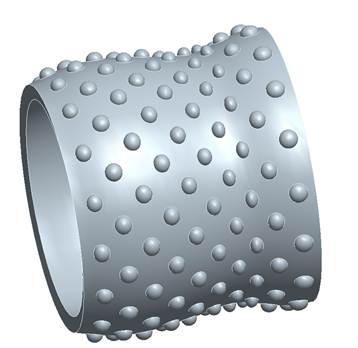
OK, here's the pattern (image attached) - a revolved spherical dimple on a revolved non cylindrical surface. I want the dimple patterned in two directions - very approximately a cylindrical grid - around the revolved surface and along the surface. Easy enough on a true cylinder but keeping the dimple following the curved surface is the tricky bit,
cheers, Sean
This thread is inactive and closed by the PTC Community Management Team. If you would like to provide a reply and re-open this thread, please notify the moderator and reference the thread. You may also use "Start a topic" button to ask a new question. Please be sure to include what version of the PTC product you are using so another community member knowledgeable about your version may be able to assist.
13 REPLIES 13
Jan 10, 2013
12:08 PM
- Mark as New
- Bookmark
- Subscribe
- Mute
- Subscribe to RSS Feed
- Permalink
- Notify Moderator
Please log in to access translation
Jan 10, 2013
12:08 PM
OK here's one solution (image attached) I've come up with - which has the added advantage of making the pattern light weight:
Created a (dimension) pattern along a curve (in this case and intersect) on the surface
Create a copy of the surfaces in the pattern and axis patterned the copy feature
Use the surfaces in a solidify. Had to do individual solidifies though for each line of revolves
(In this case the revolve is a cut and I've added the revolve diameter to vary in direction 1)
Jan 10, 2013
12:17 PM
- Mark as New
- Bookmark
- Subscribe
- Mute
- Subscribe to RSS Feed
- Permalink
- Notify Moderator
Please log in to access translation
Jan 10, 2013
12:17 PM
Hello Sean,
I would suggest that you use a TABLE pattern. I just have done some designs with an inverse dimple (like a golf ball) pattern. This works on non-cylindrical parts like an oval tube like design. Trying to simply use an axial pattern and then pattern that directionally, I would think your spacing between the dimples will change. There is a config.pro (part_table_editor excel) setting to allow you to edit your pattern table in Excel. That makes it much faster to create a table that you can control the angle and offset of your dimples per given position. For instance, your smaller diameter section may only require 15 dimples around the axis, but your larger diameter areas may require 30 dimples.
Also, have you considered a TOROIRAL bend? I just made a quick example using this, but the dimples look a little distorted.
[cid:image001.jpg@01CDEF0A.F8C2CD80][cid:image002.jpg@01CDEF0A.F8C2CD80]
Good Luck,
James
Jan 10, 2013
01:24 PM
- Mark as New
- Bookmark
- Subscribe
- Mute
- Subscribe to RSS Feed
- Permalink
- Notify Moderator
Please log in to access translation
Jan 10, 2013
01:24 PM
Project curves on surf. Pattern along curves?
Jan 10, 2013
01:27 PM
- Mark as New
- Bookmark
- Subscribe
- Mute
- Subscribe to RSS Feed
- Permalink
- Notify Moderator
Please log in to access translation
Jan 10, 2013
01:27 PM
Or create curved via intersection
May 21, 2013
10:59 AM
- Mark as New
- Bookmark
- Subscribe
- Mute
- Subscribe to RSS Feed
- Permalink
- Notify Moderator
Please log in to access translation
May 21, 2013
10:59 AM
I am modeling a panel with a punched in fan grille. The grille is made up of .115 square punches in a config of 30 wide x 26 high and a .030 space between punches. It takes about 3 mins. To generate. Is there a way to produce it to generate faster?
Thanx in advance
Paul
Thanx in advance
Paul
May 21, 2013
11:02 AM
- Mark as New
- Bookmark
- Subscribe
- Mute
- Subscribe to RSS Feed
- Permalink
- Notify Moderator
Please log in to access translation
May 21, 2013
11:02 AM
1. Use surfacing to create the shape of the cut.
2. Pattern the surfacing features.
3. Solidify the first one.
4. Pattern the solidify.
2. Pattern the surfacing features.
3. Solidify the first one.
4. Pattern the solidify.
May 21, 2013
11:04 AM
- Mark as New
- Bookmark
- Subscribe
- Mute
- Subscribe to RSS Feed
- Permalink
- Notify Moderator
Please log in to access translation
May 21, 2013
11:38 AM
- Mark as New
- Bookmark
- Subscribe
- Mute
- Subscribe to RSS Feed
- Permalink
- Notify Moderator
Please log in to access translation
May 21, 2013
11:38 AM
You can also try to change the pattern to an identical pattern. I believe it's under the 'Options' tab in the pattern dashboard. Identical patterns are much faster but don't work in every instance.
--
--
May 21, 2013
11:46 AM
- Mark as New
- Bookmark
- Subscribe
- Mute
- Subscribe to RSS Feed
- Permalink
- Notify Moderator
Please log in to access translation
May 21, 2013
11:46 AM
If you are on Creo Elements/Pro 5.0 and above, you can also use:
Edit | Geometry Pattern
In Reply to Paul Adams:
I am modeling a panel with a punched in fan grille. The grille is made up of .115 square punches in a config of 30 wide x 26 high and a .030 space between punches. It takes about 3 mins. To generate. Is there a way to produce it to generate faster?
Thanx in advance
Paul
May 21, 2013
12:20 PM
- Mark as New
- Bookmark
- Subscribe
- Mute
- Subscribe to RSS Feed
- Permalink
- Notify Moderator
Please log in to access translation
May 21, 2013
12:20 PM
If I really don't need the actual geometry but just need it on the
drawing, I sometimes create a sketch of the pattern. It looks about the
same on the drawing but regen is much faster.
T
drawing, I sometimes create a sketch of the pattern. It looks about the
same on the drawing but regen is much faster.
T
May 21, 2013
02:19 PM
- Mark as New
- Bookmark
- Subscribe
- Mute
- Subscribe to RSS Feed
- Permalink
- Notify Moderator
Please log in to access translation
May 21, 2013
02:19 PM
John is exactly right. It is doing the "Turbo" pattern but in a much simpler way. It is basically a packaged set of commands that does a surface copy, then patterns, then solidifies in one step.
Rob Reifsnyder
Mechanical Design Engineer/ Producibility Engineer / Components Engineer / Pro/E SME / Pro/E Librarian
[LM_Logo_Tag_RGB_NoR_r06]
Rob Reifsnyder
Mechanical Design Engineer/ Producibility Engineer / Components Engineer / Pro/E SME / Pro/E Librarian
[LM_Logo_Tag_RGB_NoR_r06]
May 22, 2013
07:48 AM
- Mark as New
- Bookmark
- Subscribe
- Mute
- Subscribe to RSS Feed
- Permalink
- Notify Moderator
Please log in to access translation
May 22, 2013
07:48 AM
I've gone so far as to redefining the patterned object to be a surface quilt, pattern the quilts, export/import the quilt using a strategically placed coordinate system (IGES lets you select the quilt you want to export), then do a solidify to make a one feature cut... Then the original pattern is suppressed for retrieval if changes are required (not that things ever change ;-).... Seems like a lot of work but really cuts down on the regen times......
Eric Slotty
-<">mailto:->
414-362-2552
Eric Slotty
-<">mailto:->
414-362-2552
May 22, 2013
09:33 AM
- Mark as New
- Bookmark
- Subscribe
- Mute
- Subscribe to RSS Feed
- Permalink
- Notify Moderator
Please log in to access translation
May 22, 2013
09:33 AM
In fact, with an array that big (30 X 26) you could do a pattern of a pattern using Geometry Pattern and it will really speed things up. The 26 is a little limiting, but you could do an initial Geom. Pattern of something like 5 X 13, then pattern the result of that 6X2. I did a test once on a simple square cutout patterned 50X50. Even using Geom. Pattern it took 22 minutes. Creating a 10X10 Geom. Pattern took 2 seconds, then Geom. patterning that 5X5 took 43 seconds.
Rob Reifsnyder
Mechanical Design Engineer/ Producibility Engineer / Components Engineer / Pro/E SME / Pro/E Librarian
[LM_Logo_Tag_RGB_NoR_r06]
Rob Reifsnyder
Mechanical Design Engineer/ Producibility Engineer / Components Engineer / Pro/E SME / Pro/E Librarian
[LM_Logo_Tag_RGB_NoR_r06]


