
Turn on suggestions
Auto-suggest helps you quickly narrow down your search results by suggesting possible matches as you type.
Showing results for
Please log in to access translation
Turn on suggestions
Auto-suggest helps you quickly narrow down your search results by suggesting possible matches as you type.
Showing results for
Community Tip - You can subscribe to a forum, label or individual post and receive email notifications when someone posts a new topic or reply. Learn more! X
- Community
- Creo+ and Creo Parametric
- 3D Part & Assembly Design
- Patterned sketch using centrelines in part fails w...
Translate the entire conversation x
Please log in to access translation
Options
- Subscribe to RSS Feed
- Mark Topic as New
- Mark Topic as Read
- Float this Topic for Current User
- Bookmark
- Subscribe
- Mute
- Printer Friendly Page
Patterned sketch using centrelines in part fails when part is in assembly
Mar 18, 2015
02:10 PM
- Mark as New
- Bookmark
- Subscribe
- Mute
- Subscribe to RSS Feed
- Permalink
- Notify Moderator
Please log in to access translation
Mar 18, 2015
02:10 PM
Patterned sketch using centrelines in part fails when part is in assembly
A bit of a strange one this.
I've built a part from sheetmetal which has various cutouts and holes.
One of these cutouts is for a binding post which has a notch I want to locate at a 45 degree angle.
I've added Centrelines which have been set at 45 degrees off horizontal / vertical.
I've then used those centrelines as a reference for adding the notch:
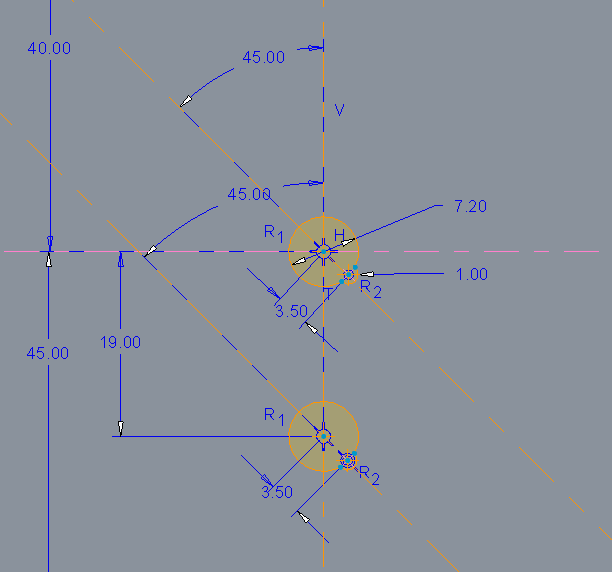
This appears to be fine.
I save the sketch then once back to the part, I extrude the sketch to generate the holes. That works fine.
I then pattern the extrusion 9 times. Again all appears OK.

I can regenerate the part, everything is fine. I save that part as "base-rear".
However now that I've used that part in an assembly "9ch-short", the assembly fails at regeneration with the following message:
9CH-SHORT regeneration completed with atypical feature or component status. Failed: 1. Child of Failed: 8.
BASE-REAR feature (ID = 9865) referenced by pattern is missing.
The Regeneration manager gives me this:
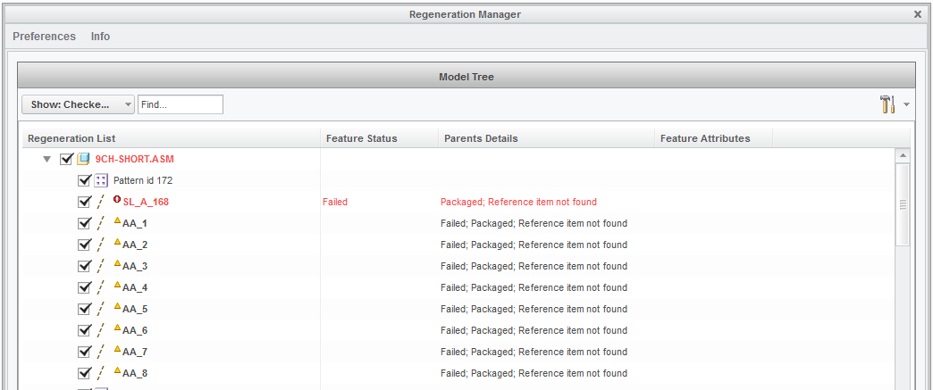
This appears to be linked to the diagonal centrelines. If I go back into the part and delete the smaller binding post cutouts with notches, the assembly is fine again.
What am I doing wrong?
This thread is inactive and closed by the PTC Community Management Team. If you would like to provide a reply and re-open this thread, please notify the moderator and reference the thread. You may also use "Start a topic" button to ask a new question. Please be sure to include what version of the PTC product you are using so another community member knowledgeable about your version may be able to assist.
Labels:
- Labels:
-
Assembly Design
4 REPLIES 4
Mar 18, 2015
02:18 PM
- Mark as New
- Bookmark
- Subscribe
- Mute
- Subscribe to RSS Feed
- Permalink
- Notify Moderator
Please log in to access translation
Mar 18, 2015
02:18 PM
In fact, I take it back.
Having deleted those additional holes, I still have the issue.
Maybe it's something else...
So it's a more open question: how do I go about identifying the root of the issue and resolving it? I can't see where SL_A_168 comes from.
Mar 18, 2015
05:55 PM
- Mark as New
- Bookmark
- Subscribe
- Mute
- Subscribe to RSS Feed
- Permalink
- Notify Moderator
Please log in to access translation
Mar 18, 2015
05:55 PM
Found the cause 
It's actually with some other circle holes in the corners of the big one (for an Neutrik XLR D-shell cutout). Nothing to do with the diagonal lines / binding post holes I mentioned earlier.
There are no issues whilst those holes are there.
But as soon as I remove them, that's where the problem starts.
It's strange because those holes don't reference anything else, and every other dimension is defined and not weak.
The problem is still there if I remove the pattern for the 9 sets of cutouts.
If I delete the entire sketch (and extrusion), the problem remains ?!?
There are no other parts in the assembly that use those holes as reference, so I really can't see why there's a problem.
It might just be easier to start a new assembly, but it's a bit of a pain as there's quite a lot to it and will take a good few hours.
edit: maybe it's my assembly file that has become corrupt somehow. Is there a way I can do a healthcheck on it and clean out any old / irrelevant data that might be the cause of the issue?
Mar 18, 2015
06:58 PM
- Mark as New
- Bookmark
- Subscribe
- Mute
- Subscribe to RSS Feed
- Permalink
- Notify Moderator
Please log in to access translation
Mar 18, 2015
06:58 PM
I've had very stubborn references in the past. Almost like they are history related. I still wish errors were a little easier to track down.
Mar 24, 2015
04:13 PM
- Mark as New
- Bookmark
- Subscribe
- Mute
- Subscribe to RSS Feed
- Permalink
- Notify Moderator
Please log in to access translation
Mar 24, 2015
04:13 PM
In the end, I recreated the part and remade the whole assembly. A bit time consuming, but at least problem is gone.


