
Turn on suggestions
Auto-suggest helps you quickly narrow down your search results by suggesting possible matches as you type.
Showing results for
Please log in to access translation
Turn on suggestions
Auto-suggest helps you quickly narrow down your search results by suggesting possible matches as you type.
Showing results for
Community Tip - Your Friends List is a way to easily have access to the community members that you interact with the most! X
- Community
- Creo+ and Creo Parametric
- 3D Part & Assembly Design
- Questions regarding automatic feature creation and...
Translate the entire conversation x
Please log in to access translation
Options
- Subscribe to RSS Feed
- Mark Topic as New
- Mark Topic as Read
- Float this Topic for Current User
- Bookmark
- Subscribe
- Mute
- Printer Friendly Page
Questions regarding automatic feature creation and making cuts at feature intersections
Mar 02, 2013
01:45 PM
- Mark as New
- Bookmark
- Subscribe
- Mute
- Subscribe to RSS Feed
- Permalink
- Notify Moderator
Please log in to access translation
Mar 02, 2013
01:45 PM
Questions regarding automatic feature creation and making cuts at feature intersections
- I have a skeleton model consisting of only datum points and curves (Picture 1). Every datum curve represents a tube or rod with 1" OD, and my plan for creating the tubes or rods is to make a swept feature on each curve. The only parameter that will change from rod to rod is length. Is it possible to automate this process in some way?
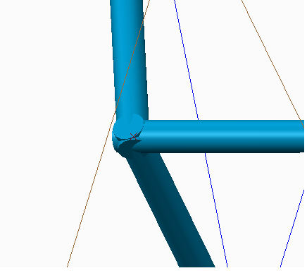
- I'd like to cut away the excess material at tube intersections so that I am left with good looking corners. Picture 2 is an example of the material I am wanting to get rid of. What is the best way of achieving this?
I apologize if these are very basic issues. I am a student at university with much to learn!
Thanks for your help.
r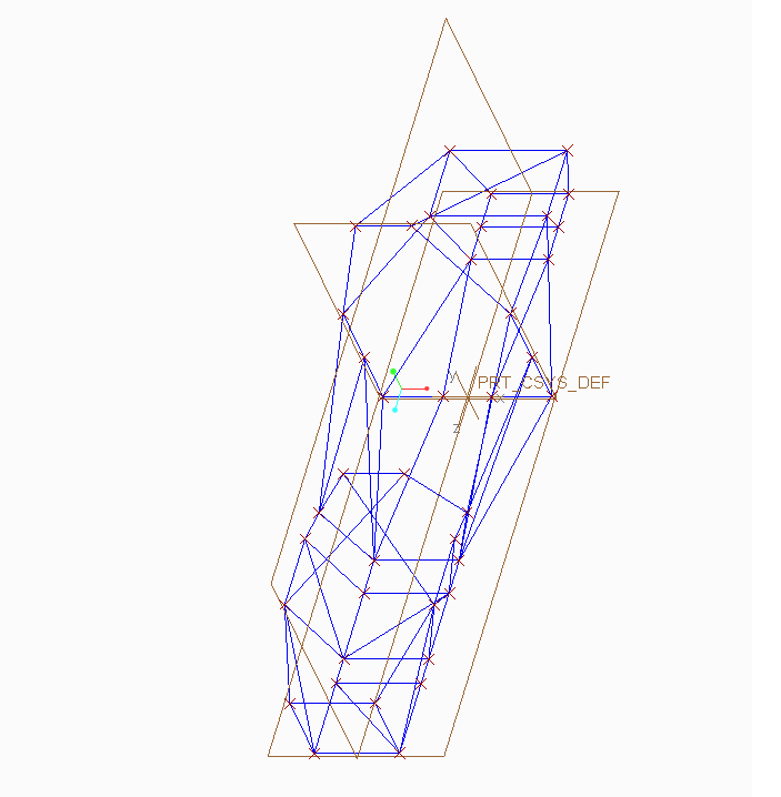
This thread is inactive and closed by the PTC Community Management Team. If you would like to provide a reply and re-open this thread, please notify the moderator and reference the thread. You may also use "Start a topic" button to ask a new question. Please be sure to include what version of the PTC product you are using so another community member knowledgeable about your version may be able to assist.
Solved! Go to Solution.
Labels:
- Labels:
-
General
ACCEPTED SOLUTION
Accepted Solutions
Mar 04, 2013
03:46 AM
- Mark as New
- Bookmark
- Subscribe
- Mute
- Subscribe to RSS Feed
- Permalink
- Notify Moderator
Please log in to access translation
Mar 04, 2013
03:46 AM
You can work with parameters and relations, and if needed with family tables to make your skeleton dynamic and easily adjustable by altering just some parameters.
The connections is another story.
One possibility is to make all tubes shorter and leave the corners empty. In an assembly you can add corner parts that can by dynamic so they adjust to the ribs
Another is creating UDF's to do this
Or, if you make all rod ends fully round, I suppose they will also intersect correctly (if all diameters are the same)
Or, you can use the EFX extension. This addon provides all functionality you require.
7 REPLIES 7
Mar 02, 2013
02:03 PM
- Mark as New
- Bookmark
- Subscribe
- Mute
- Subscribe to RSS Feed
- Permalink
- Notify Moderator
Please log in to access translation
Mar 02, 2013
02:03 PM
A couple of observations: Most frameworks will be a primary tube bent at intersections with struts welded between them. This requires a little more planning than you have currently done with the skeleton.
If each of these are individual parts, you must treat each end in relation to the mate. Normally, you would want to detail each rod to show how it is actually cut for fabrication prior to welding. You can use the skeleton model to provide vectors for each cut.
If this is simply a concept model, you can place spheres at the joints and extrude the rod to the skeleton's line endpoints.
You can also look up the "pipe" command. This will help make bends in the geometry if you wish. Pipes are driven by points and create straight vectors between the points and will create the appropriate bend radii when the more than 2 points are specified. Points can be line ends. They do not necessarily need to be point features.
You can make a flexible part of the tube and constrain them in an assembly using the skeleton model. I have not done this but there are tutorials on how this is done.
Mar 04, 2013
03:46 AM
- Mark as New
- Bookmark
- Subscribe
- Mute
- Subscribe to RSS Feed
- Permalink
- Notify Moderator
Please log in to access translation
Mar 04, 2013
03:46 AM
You can work with parameters and relations, and if needed with family tables to make your skeleton dynamic and easily adjustable by altering just some parameters.
The connections is another story.
One possibility is to make all tubes shorter and leave the corners empty. In an assembly you can add corner parts that can by dynamic so they adjust to the ribs
Another is creating UDF's to do this
Or, if you make all rod ends fully round, I suppose they will also intersect correctly (if all diameters are the same)
Or, you can use the EFX extension. This addon provides all functionality you require.
Mar 07, 2013
10:05 AM
- Mark as New
- Bookmark
- Subscribe
- Mute
- Subscribe to RSS Feed
- Permalink
- Notify Moderator
Please log in to access translation
Mar 07, 2013
10:05 AM
EFX is the perfect solution; thanks for telling me about it. With a little research on the extension, I came across the PTC SAE Sponsorship ( http://www.ptc.com/company/community/education/sponsorship/ ), which offers a free academic version of Creo 2.0 that includes EFX.
Thanks again! This is going to cut weeks off of frame design.
Mar 07, 2013
10:21 AM
- Mark as New
- Bookmark
- Subscribe
- Mute
- Subscribe to RSS Feed
- Permalink
- Notify Moderator
Please log in to access translation
Mar 07, 2013
10:21 AM
It is indeed a very powerful tool.
Once you'll get familiar with it, building frames and making changes to existing frames should be a piece of cake.
I'm glad I could help.
Mar 07, 2013
10:24 AM
- Mark as New
- Bookmark
- Subscribe
- Mute
- Subscribe to RSS Feed
- Permalink
- Notify Moderator
Please log in to access translation
Mar 07, 2013
10:24 AM
... and here is the Wallpapers for you: Do not forget for Creo Advanced Framework 
Vladimir
Best Regards,
Vladimir Palffy
Vladimir Palffy
Mar 04, 2013
01:02 PM
- Mark as New
- Bookmark
- Subscribe
- Mute
- Subscribe to RSS Feed
- Permalink
- Notify Moderator
Please log in to access translation
Mar 04, 2013
01:02 PM
What I've done for similar things is sweep surfaces at the assembly (or skeleton or inheritance) level. Then you can create individual parts with tube protrusions and use these surfaces at the top level to determine OD and wall thickness, and use them to trim the tubes as needed.
Mar 07, 2013
03:23 AM
- Mark as New
- Bookmark
- Subscribe
- Mute
- Subscribe to RSS Feed
- Permalink
- Notify Moderator
Please log in to access translation
Mar 07, 2013
03:23 AM
I suggest use Framework Extension for Creo - here is short video tutorial for you:
Quick EFX (Expert Framework Extension) video tutorial
Regards,
Vladimir
Best Regards,
Vladimir Palffy
Vladimir Palffy


