
Turn on suggestions
Auto-suggest helps you quickly narrow down your search results by suggesting possible matches as you type.
Showing results for
Please log in to access translation
Turn on suggestions
Auto-suggest helps you quickly narrow down your search results by suggesting possible matches as you type.
Showing results for
Community Tip - You can subscribe to a forum, label or individual post and receive email notifications when someone posts a new topic or reply. Learn more! X
- Community
- Creo+ and Creo Parametric
- 3D Part & Assembly Design
- Setting start and finish conditions for Assembly
Translate the entire conversation x
Please log in to access translation
Options
- Subscribe to RSS Feed
- Mark Topic as New
- Mark Topic as Read
- Float this Topic for Current User
- Bookmark
- Subscribe
- Mute
- Printer Friendly Page
Setting start and finish conditions for Assembly
Jan 25, 2017
08:15 AM
- Mark as New
- Bookmark
- Subscribe
- Mute
- Subscribe to RSS Feed
- Permalink
- Notify Moderator
Please log in to access translation
Jan 25, 2017
08:15 AM
Setting start and finish conditions for Assembly
I use basic assembly a lot for viewing models in position. I haven't however got anywhere with establishing movements or start or end positions within the assembly. There are a lot of basics I might be missing.
Is there any best practice for setting up start and end conditions in an assembly.
In Google searching this topic I see that there appear to be various methods to go about the same subject. I've seen;
1) Snapshots
2) Family Tables and even
3) Some kind of relational constraining
Some of my search results were for use in Wildfire, what would be the best way this would be accomplished using the up to date Creo software?
Labels:
- Labels:
-
Assembly Design
4 REPLIES 4
Jan 25, 2017
04:21 PM
- Mark as New
- Bookmark
- Subscribe
- Mute
- Subscribe to RSS Feed
- Permalink
- Notify Moderator
Please log in to access translation
Jan 25, 2017
04:21 PM
In playing around with this more it would seem that if I could use the slider constraint option that I would be able to select max and min movement of assembled components.
The only problem is that the slider option requires an axis and the movement really doesn't include a corresponding axis to apply with.
Is there a way to define a max and min translated stroke movement without using an axis?
Jan 25, 2017
05:55 PM
- Mark as New
- Bookmark
- Subscribe
- Mute
- Subscribe to RSS Feed
- Permalink
- Notify Moderator
Please log in to access translation
Jan 25, 2017
05:55 PM
Using a slider constraint will work well if you can set up the slide-direction axes and the datums to control the motion limits.
But maybe that's not feasible because you can't revise your models.
Just keep in mind that you can also use edges and surfaces to define these types of joints.
However, it's not that onerous to use a combination of 2 planar constraints, and this a general and flexible slider connection:
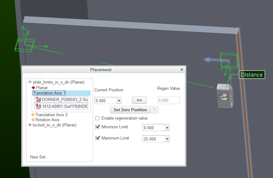
Note: the 2nd planar constraint is required because you can't simultaneously specify 0 for the min and max motion limits.
Jan 26, 2017
09:49 AM
- Mark as New
- Bookmark
- Subscribe
- Mute
- Subscribe to RSS Feed
- Permalink
- Notify Moderator
Please log in to access translation
Jan 26, 2017
09:49 AM
Paul
Your use of Slider looks a little different than my instance using the criteria that populates by default.
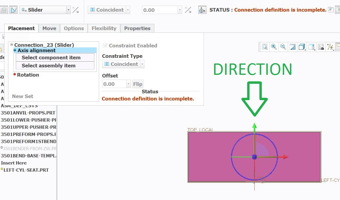
I would like to slide the box from it's 0 position to 5 at the end of the cycle in the direction shown with the green arrow.
My example shows up different in respect that yours shows translation axis and mine shows axis alignment. I don't know what to pick for "Axis alignment". This just seems unselectable.
Also I just don't know how to contend with the "Rotation" which appears to be necessary. The green arrow does show an actual axis, but there is no corresponding axis on the rest of the assembly. I think you might be suggesting that I could use an edge. If I could get the 1st part to work perhaps the 2nd would also work.
Jan 26, 2017
10:31 AM
- Mark as New
- Bookmark
- Subscribe
- Mute
- Subscribe to RSS Feed
- Permalink
- Notify Moderator
Please log in to access translation
Jan 26, 2017
10:31 AM
Well, in my screenshot, I wasn't using a slider connection.
I think you have to do some tutorials and read the help about assembly constraint sets to progress.
Here's a link to the help page about constraints: Creo Parametric Help Center
Here's a link to a tutorial that covers many types of connections: Tutorial: Assembling a Mechanism Using Connection Sets
You have to understand these concepts before you can assign to your assembly components motion limits or servo motor controls.


