Community Tip - Need to share some code when posting a question or reply? Make sure to use the "Insert code sample" menu option. Learn more! X
- Community
- Creo+ and Creo Parametric
- 3D Part & Assembly Design
- Simple Sweep fails to generate
- Subscribe to RSS Feed
- Mark Topic as New
- Mark Topic as Read
- Float this Topic for Current User
- Bookmark
- Subscribe
- Mute
- Printer Friendly Page
Simple Sweep fails to generate
- Mark as New
- Bookmark
- Subscribe
- Mute
- Subscribe to RSS Feed
- Permalink
- Notify Moderator
Simple Sweep fails to generate
Hi, I'm trying to sweep a Powdered Metal Chamfer around the the profile of an involute gear tooth profile. I have tried several times with no luck. It either fails to generate or gives me an error that says something about changing the part accuracy. tried to mess with the accuracy and just made other features fail.
1. I'm not familiar with what the accuracy pertaining to creo is/does
2. Any help or rules of thumb with sweeps and this particular sweep would be greatly appreciated
attached is the profile i am trying to sweep this profie around
Thanks!
This thread is inactive and closed by the PTC Community Management Team. If you would like to provide a reply and re-open this thread, please notify the moderator and reference the thread. You may also use "Start a topic" button to ask a new question. Please be sure to include what version of the PTC product you are using so another community member knowledgeable about your version may be able to assist.
- Labels:
-
General
- Mark as New
- Bookmark
- Subscribe
- Mute
- Subscribe to RSS Feed
- Permalink
- Notify Moderator
Creo 1.0 or 2.0?
You might try "absolute accuracy". It might be choking on that little inside corner.
Relative accuracy has already proven to be a PITA!
But to set absolute accuracy, you have to jump through a few hoops.
Config.pro:
enable_absolute_accuracy yes
default_absolute_accuracy <value> {recommend .00005 depending on units}
you might also tighten up relative accuracy:
accuracy_lower_bound .000001 {best case}
Accuracy was introduced to speed up several large part/assembly file loading issues. But the defaults really messes with familiar behavior.
Next:
FILE/PREPARE/MODEL PROPERTIES/ACCURACY - change
change Relative to Absolute and provide a reasonable value.
The dialog will let you regenerate to see if it will work at the given value.
One thing I noticed that will blow up is text in sketches unless it is the default font.
Also note that relative accuracy is calculated from the part's bounding region. I find it absolutely inhibiting for most of my work.
Can you sense my frustration in the default implementation? ![]()
- Mark as New
- Bookmark
- Subscribe
- Mute
- Subscribe to RSS Feed
- Permalink
- Notify Moderator
Hello,
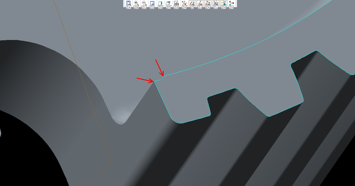
I think you could also have a problem of overlapping geometry in these areas (see picture).

- Mark as New
- Bookmark
- Subscribe
- Mute
- Subscribe to RSS Feed
- Permalink
- Notify Moderator
That the "inside corner" I was referring to. If appropriate for the model, maybe "machine" this feature after the chamfer?
Of course, the tool must do what the user needs. Sometimes this requires several features to get there. Being sintered metal, the manufacturer's tool is probably plunge-EDM'd so there really is no "tool" limitation to the forming of this part.
- Mark as New
- Bookmark
- Subscribe
- Mute
- Subscribe to RSS Feed
- Permalink
- Notify Moderator
I'd actually try and fix that little geometry glitch as well. Does it absolutely HAVE to be there? Also, maybe try doing it as 2 separate sweeps?
- Mark as New
- Bookmark
- Subscribe
- Mute
- Subscribe to RSS Feed
- Permalink
- Notify Moderator
Thanks for all the info. I ended up abandoning the sweep and doing an extrude and a draft which worked. (the extrude was for the flat and the draft created the chamfer since i could not get the chamfer tool to work around that small feature either.)
Again thanks for the insight and help!
- Mark as New
- Bookmark
- Subscribe
- Mute
- Subscribe to RSS Feed
- Permalink
- Notify Moderator
Note that if you have parts that interface with each other set to different accuracies in Creo, you will probably run into headaches when you get into assembly mode.
I made a default.prt and default.asm, set the accuracy on them to absolute with a smaller decimal, dropped them somewhere safe (NOT m010/.../formats or standards etc unless you want to do it again when the next release comes out, also keep a backup folder of your formats and config.pro somewhere safe if you insist on putting new .frm files in the m010/.../formats folder for easy access) and modified my config.pro settings to use those as the new part defaults.
Not only have I not had any more accuracy issues, but once I changed the defaults, I also never had to silently swear to myself, open up a part that was failing to mate in assembly mode, change the accuracy, regenerate, save, close, regenerate and have the constraints work.


