

Question
Tip of the Month Excerpt from the PTC Technical Specialists E-Newsletter September 2010 Edition
You can download the complete newsletter, w/ this portion authored by Matt Mason, by clicking here.
| Tip of the Month |
Pro/ENGINEER Visibility Study Analysis Feature |
|---|
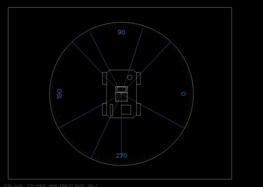
This section is intended to outline the steps required to set up an assembly level visibility study. The resulting analysis feature will show distinct “visible” and “non-visible” lines of sight. Downstream deliverables include a saved analysis feature and a 2D drawing. *Note: Pro/ENGINEER’s Behavioral Modeling Extension (BMX) is required…* More notes are included at the end of this section…
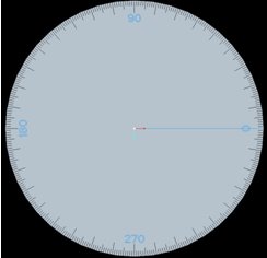
- Start by creating a “Visibility Study” assembly in Pro/E. This assembly has a generic “Ground” component with graduated markings used to measure visibility angles. There is also a collection of datum curves that can be modified to match the final analysis results and subsequently passed to a 2D drawing.
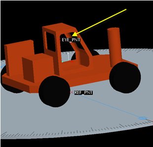
- Add the desired product assembly (a solid shrinkwrap or envelope component can be used in place of a top-level assembly) to the Visibility_Study assembly.
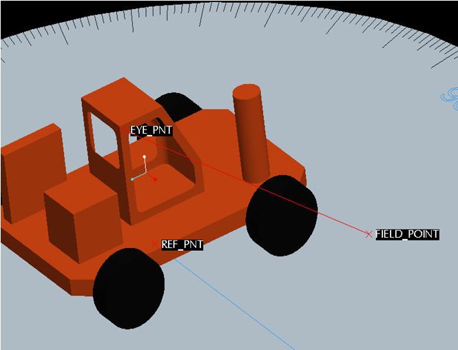
- Make sure that the product assembly has a datum point for the operator’s eye location
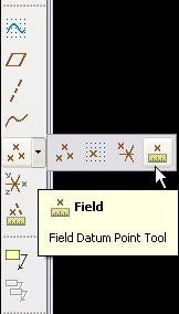
- Add a Field Point to the Visibility_Study assembly.
- Field Points are found in the datum point flyout menu
- Field Points are found in the datum point flyout menu
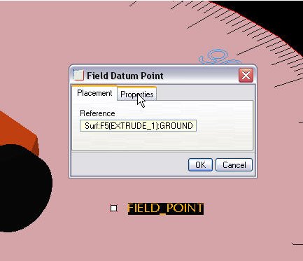
- Place the Field Point on the top surface of the Ground.prt. Location of the field point on the surface is not critical. Rename the newly created point “FIELD_POINT” to help differentiate from any existing points in the assembly.
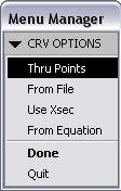
- Create a new Datum Curve
 to connect the Eye Point to the Field Point.
- Keep the defaults that appear in the menu manager and click Done.
- Keep the defaults that appear in the menu manager and click Done.
- While holding the Ctrl key, select the Eye Point and the Field Point. Click OK, Done, OK to close the menu manager and create the new datum curve
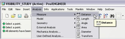
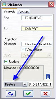
- Create an Analysis Feature to measure the distance between the newly created datum curve and the product assembly.
- Analysis > Measure > Distance from the Pro/E toolbar.
- Analysis > Measure > Distance from the Pro/E toolbar.
- Measure From: Datum Curve, To: Product Part/Assembly/Shrinkwrap/Envelope, etc…
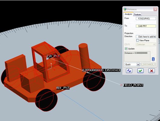
- Change the Analysis type to “Feature” and click the Green Checkbox to complete the feature.
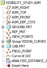
- The following three features should be in consecutive order in the model tree:
- FIELD_POINT
- Curve id xxx
- ANALYSIS_DISTANCE_1
- FIELD_POINT
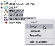
- Select the three features mentioned above and group them together to create a new UDA group feature in the model tree.
- Select the three features, Right-Click in the model tree and choose Group from the Right Mouse button menu
- Select the three features, Right-Click in the model tree and choose Group from the Right Mouse button menu
- Create a new User-Defined Analysis to see the line of sight analysis for the assembly.
- Select Analysis > User-Defined Analysis… from the Pro/E toolbar
- Select Analysis > User-Defined Analysis… from the Pro/E toolbar
- In the User-Defined Analysis window, leave the settings proved as their default values.
- Expand the “Computation Settings” and “Saved Analyses” drop-down menus.
- Type a new name for the saved analysis feature and click the “Save” icon to store it
- Expand the “Computation Settings” and “Saved Analyses” drop-down menus.
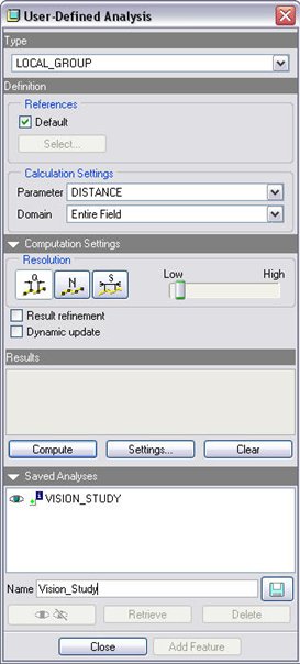
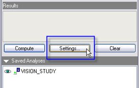
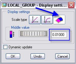
- Click the “Settings…” button in the results section to change the analysis settings.
- Change the Display Setting to “Two color shading” as well as changing the “Middle value” to .01. Click OK when finished.
- Click the “Compute” button to run the analysis.
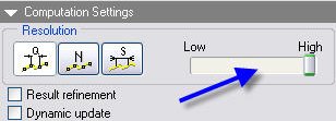
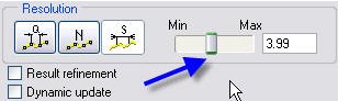
- The accuracy of the analysis can be adjusted in several ways.
- When using a “Quality” based analysis, the scope can be set from Low to High
- When using a “Quality” based analysis, the scope can be set from Low to High
- When using a “Numeric” analysis, the number of points can be adjusted from 0 to 100
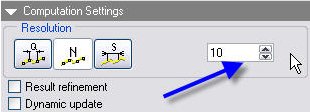
- When using a “Step” analysis, the increment between measurements can be adjusted
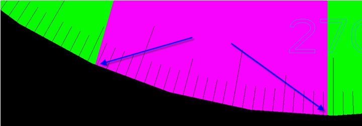
- When the analysis is complete, choose “Add Feature” to place the analysis feature in the model tree.
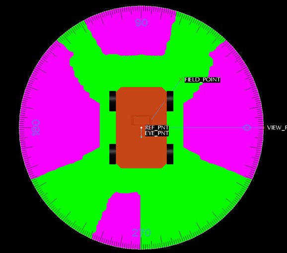
- With the analysis results still displayed on the screen, note where the green/purple boundary lines match the scale tick marks.
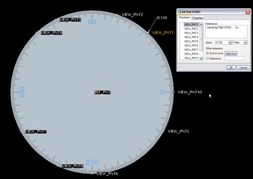
- Select VIEW_POINTS from the model tree and Edit Definition to change the point locations
- Move the point locations to match the markings noted in step 17.
- Create a new drawing and place the Visibility Assembly study. Use the TOP view to display the newly created line of sight indicators. Hide any excess curves as needed.
** General Notes **
- The analysis feature is NOT persistent, meaning it will not show up in a drawing, or during the redefinition of existing features in the assembly
- The same analysis feature can be reused for different settings of the EYE POINT
- In order to delete the analysis group in the model tree, you must first delete the saved analysis from the Analysis > Saved Analysis menu
- If using a shrinkwrap, best results are obtained by creating a shrinkwrapped solid; also make sure to include any necessary datum features
- To improve analysis time and resolution of the analysis feature, the surface of the “GROUND.PRT” can be divided into any desired number of separate surfaces (i.e. quadrants)
- 64-bit machines are recommended for larger/more complex assemblies
- More information can be found by searching for “user defined analysis” in the Pro/E Help menu as well as the Behavioral Modeling Analysis Pro/E Help Topic Collection PDF
You can download the complete newsletter, w/ this portion authored by Matt Mason, by clicking here.
This thread is inactive and closed by the PTC Community Management Team. If you would like to provide a reply and re-open this thread, please notify the moderator and reference the thread. You may also use "Start a topic" button to ask a new question. Please be sure to include what version of the PTC product you are using so another community member knowledgeable about your version may be able to assist.