
Turn on suggestions
Auto-suggest helps you quickly narrow down your search results by suggesting possible matches as you type.
Showing results for
Please log in to access translation
Turn on suggestions
Auto-suggest helps you quickly narrow down your search results by suggesting possible matches as you type.
Showing results for
Community Tip - Your Friends List is a way to easily have access to the community members that you interact with the most! X
- Community
- Creo+ and Creo Parametric
- 3D Part & Assembly Design
- Trouble creating Extruded Cut
Translate the entire conversation x
Please log in to access translation
Options
- Subscribe to RSS Feed
- Mark Topic as New
- Mark Topic as Read
- Float this Topic for Current User
- Bookmark
- Subscribe
- Mute
- Printer Friendly Page
Trouble creating Extruded Cut
Jul 21, 2011
09:58 AM
- Mark as New
- Bookmark
- Subscribe
- Mute
- Subscribe to RSS Feed
- Permalink
- Notify Moderator
Please log in to access translation
Jul 21, 2011
09:58 AM
Trouble creating Extruded Cut
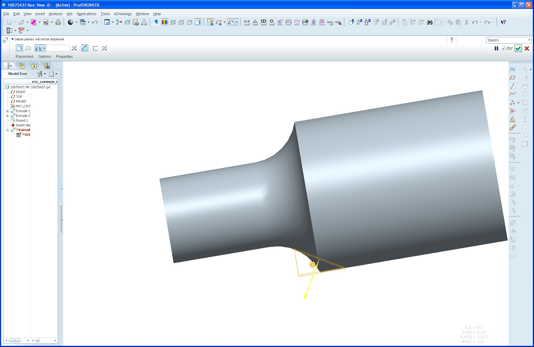
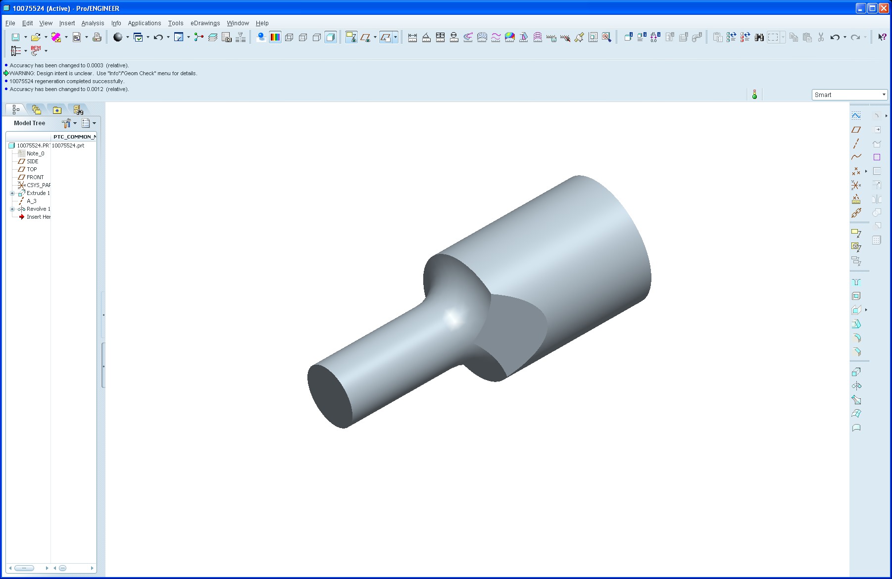
I am having trouble creating and extruded cut. I have been using Pro/E since 1993 or so and consider myself an experienced user of the package and I am getting really frustrated that I am not able to create this cut. I have tried everything I could think of to get it to work with little success.
I have attached a simplified version of the model from WF 5.0. Here is a list of things that I have tried:
Didn't work:
- Modified accuracy both directions
- Changed radius of round feature
- Creating it as a Blind feature
- One Direction only
- Open sketch
- Closed sketch
- Creating surfaces and merging
- Different angles
- Created a Datum plane where I want the angled surface, and tried to solidify using that plane (realizing that it would shave off part of the smaller cylinder)
Worked, but not satisfied:
- removed tangency to round feature in the sketch. Feature generated but is not exactly tangent because of created weak dimension.
I tried to create a projected curve of the angled line and was able to see that the projected curve didn't meet up at the tangency point. I am figuring that this issue has something to do with the fact that I am trying to cut tangent to the radius, but I would think that with all that I have tried it would be able to create the cut. What makes it odd is that removing the tangency constraint in the sketch allows the dimension to shift ~.0003" and it seems to work then, but then I am guessing that the cut doesn't go exactly tangent to the radius and that is why it is working then.
Any thoughts out there?
-Greg
This thread is inactive and closed by the PTC Community Management Team. If you would like to provide a reply and re-open this thread, please notify the moderator and reference the thread. You may also use "Start a topic" button to ask a new question. Please be sure to include what version of the PTC product you are using so another community member knowledgeable about your version may be able to assist.
Solved! Go to Solution.
Labels:
- Labels:
-
2D Drawing
ACCEPTED SOLUTION
Accepted Solutions
Jul 22, 2011
02:23 PM
- Mark as New
- Bookmark
- Subscribe
- Mute
- Subscribe to RSS Feed
- Permalink
- Notify Moderator
Please log in to access translation
11 REPLIES 11
Jul 21, 2011
10:12 AM
- Mark as New
- Bookmark
- Subscribe
- Mute
- Subscribe to RSS Feed
- Permalink
- Notify Moderator
Please log in to access translation
Jul 21, 2011
10:12 AM
Don't know if this will help, but:
- I created a test model from scratch (arbitrary, metric dimensions) and created the extrude successfully. However, I'd used a full (90°) round - i.e., the round size was less than the step height.
- I then changed the round to a larger value, to make (effectively) an edge-to-surface round like you have. Not only did my extrude sketch lose its reference to the round silhouette, but the whole cut then failed just as you've found.
Weird.
How about extruding your basic profile, then turning the round bits? A bodge, but it might work...
Jul 21, 2011
11:00 AM
- Mark as New
- Bookmark
- Subscribe
- Mute
- Subscribe to RSS Feed
- Permalink
- Notify Moderator
Please log in to access translation
Jul 21, 2011
11:00 AM
Jonathan,
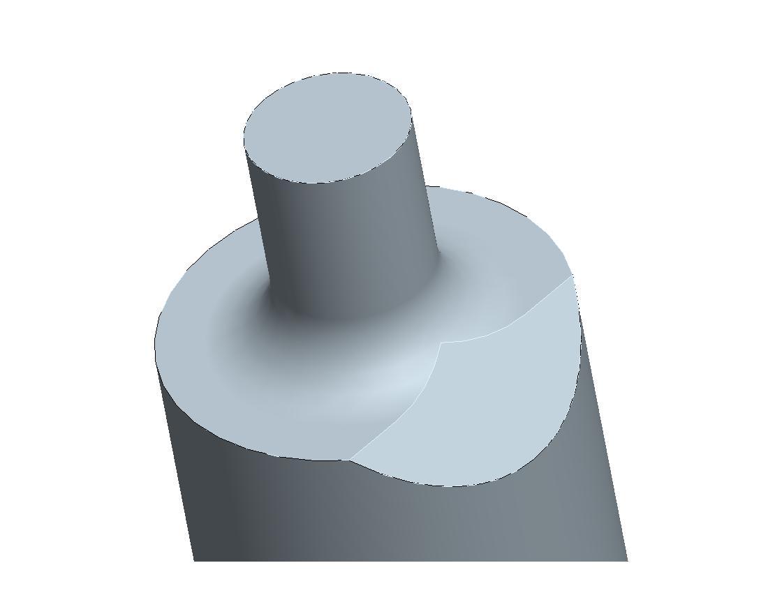
Thanks for your response. Weird Huh? I tried what I think that you were describing by creating the outer profile as an extrude, and then creating a revolved cut to create the round part. Something really weird happens when I add the revolved CUT. It actually adds material to bury the flats and end up with the base geometry to which I would have to add an extruded cut to get the flats back?????
EXTRUDED BASE
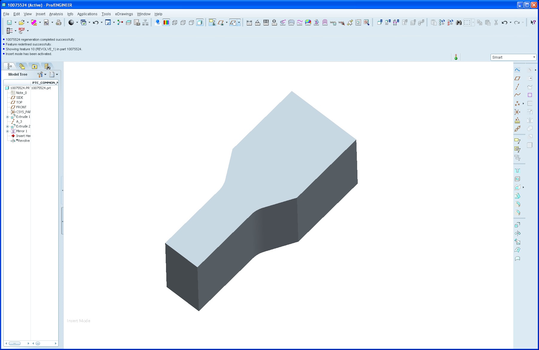
REVOLVED CUT
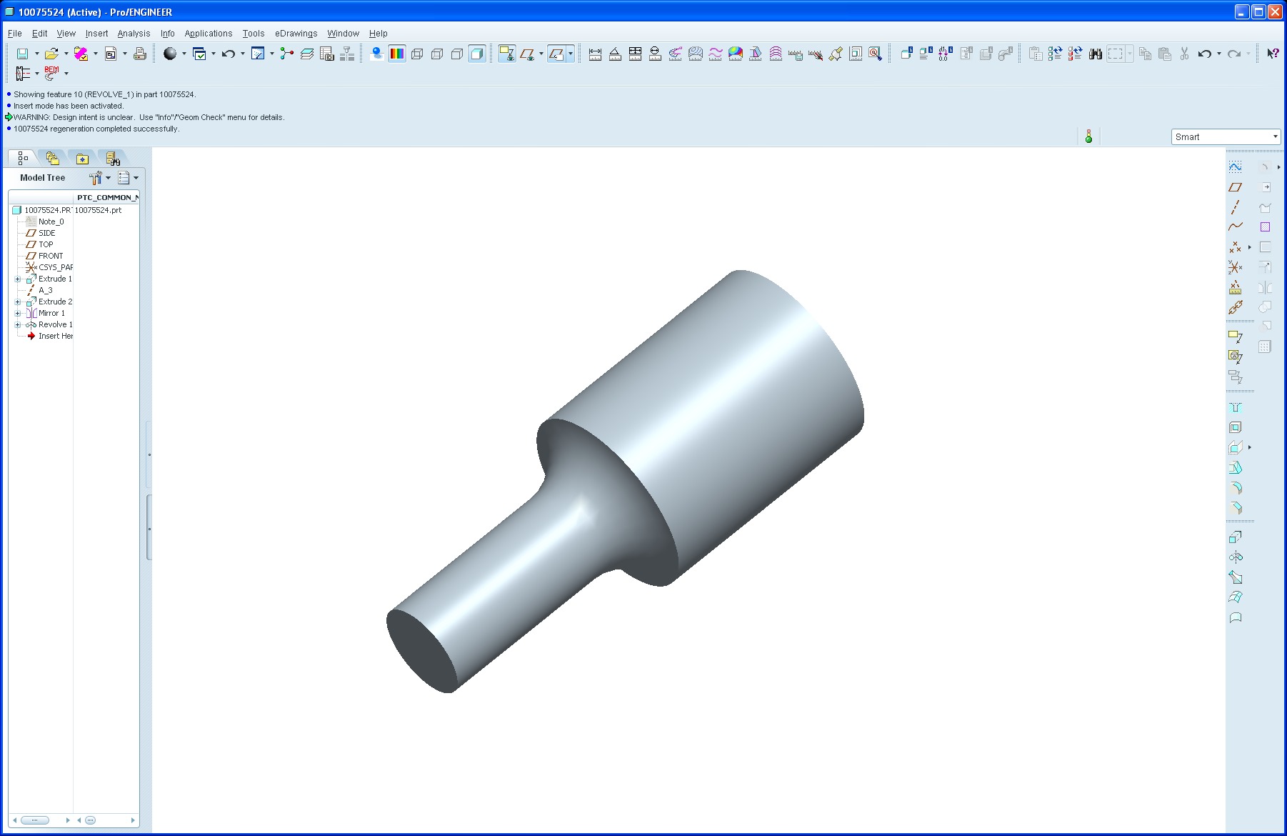
NOTICE WHERE ORIGINAL CUTS ARE
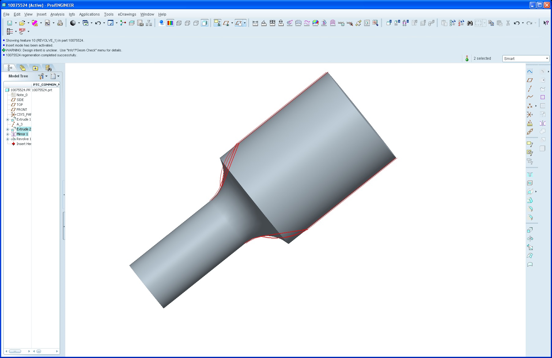
Very Weird!
-Greg
Jul 21, 2011
11:14 AM
- Mark as New
- Bookmark
- Subscribe
- Mute
- Subscribe to RSS Feed
- Permalink
- Notify Moderator
Please log in to access translation
Jul 21, 2011
11:14 AM
OK, here's a (slightly) better one.
Include the revolve in your first sketch so that it passes beyond your final diameter and extends into a flat face.
Then create the extruded cut(s).
Then create a revolved cut to trim down to your final diameter.
Seems to work for me... :fingerscrossed:
Jul 22, 2011
08:57 AM
- Mark as New
- Bookmark
- Subscribe
- Mute
- Subscribe to RSS Feed
- Permalink
- Notify Moderator
Please log in to access translation
Jul 22, 2011
08:57 AM
I gave it a go, and it seems like it does behave better when allowing that radius to travel the full 90°. I still notice however, that the range of flexibility is still limited. Do you notice the same thing. It seems like it works pretty well around 45° angle, and maybe up to 10 degrees steeper, and then seems to be a little more flexible at the shallower angles.
-Greg
Jul 21, 2011
11:18 AM
- Mark as New
- Bookmark
- Subscribe
- Mute
- Subscribe to RSS Feed
- Permalink
- Notify Moderator
Please log in to access translation
Jul 21, 2011
11:18 AM
So then I thought that maybe it would have been better if I hadn't created the cuts as separate features. I rebuilt the initial extrude feature to include the cut geometry, and then added the revolve. After creating the revolved cut, I thought I had success until I looked at the other side of the model, and it left the cut geometry like I wanted on the front side, and then covered the flat on the back side. I thought Accuracy! so I changed the relative accuracy to .0003". I will let you try that and see what you get.....
(hint) the flat is covered on the front and the flat is left exposed on the back.
-Greg
Jul 21, 2011
01:29 PM
- Mark as New
- Bookmark
- Subscribe
- Mute
- Subscribe to RSS Feed
- Permalink
- Notify Moderator
Please log in to access translation
Jul 21, 2011
01:29 PM
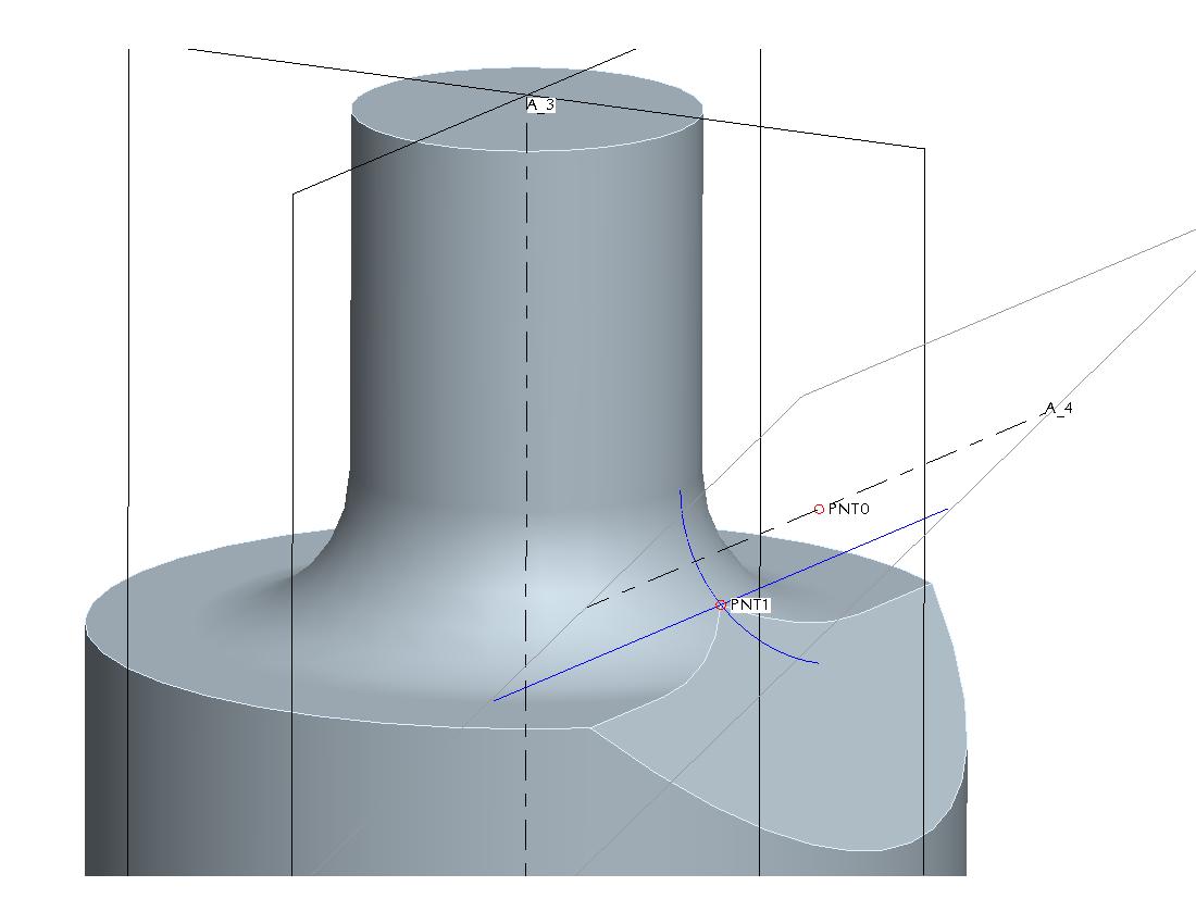
Gregory,
Is this what you're trying to do?
I think the problem may be that that little single-point singularity makes things go haywire with solid features. Reminds me of other things, such
as certain round types, that worked once upon a time, but no more. Anyway, I did the above with surfaces, 3 to be exact. Create a revolved surface for the main neck-and-round geometry. Create a Both Sides flat surface extending beyond the shaft laterally and along the inclined direction. You can easily make that tangent by picking the profile of the round as a reference in the Sketch. Now create an extruded surface duplicating the outside of the main shaft itself. Trim the angled flat surface with the cylindrical surface, then Merge the result with the revolved surface, then Solidify.
David
Jul 21, 2011
02:13 PM
- Mark as New
- Bookmark
- Subscribe
- Mute
- Subscribe to RSS Feed
- Permalink
- Notify Moderator
Please log in to access translation
Jul 21, 2011
02:13 PM
And here it is using regular solild features:
Create the neck and round using solid features. Now Copy the edge of the round in a sketch to create the curve shown. Create a Point at its center, an Axis through the point perpendicular to the plane of the curve, and an angled Plane through the axis. Create another Point where the Plane crosses the Curve. Now sketch on the angled plane and sketch the straight line shown. Extrude it outward and Remove Material.
David
Jul 22, 2011
08:47 AM
- Mark as New
- Bookmark
- Subscribe
- Mute
- Subscribe to RSS Feed
- Permalink
- Notify Moderator
Please log in to access translation
Jul 22, 2011
08:47 AM
I have recreated the geometry by this method. Seems like it works to an extent for me. It does still seem to have its boundaries when it works which seem to be far less flexible than I would imagine it being. Does your method still work for you when the radius stops short of a full 90°? I have my radius running out along the edge of the bigger diameter. Seems like if I allow the radius to continue the full 90° the model is a little more stable and predictable.
Thanks for looking into this with me,
-Greg
Jul 22, 2011
02:21 PM
- Mark as New
- Bookmark
- Subscribe
- Mute
- Subscribe to RSS Feed
- Permalink
- Notify Moderator
Please log in to access translation
Jul 22, 2011
02:21 PM
Yep, still works fine: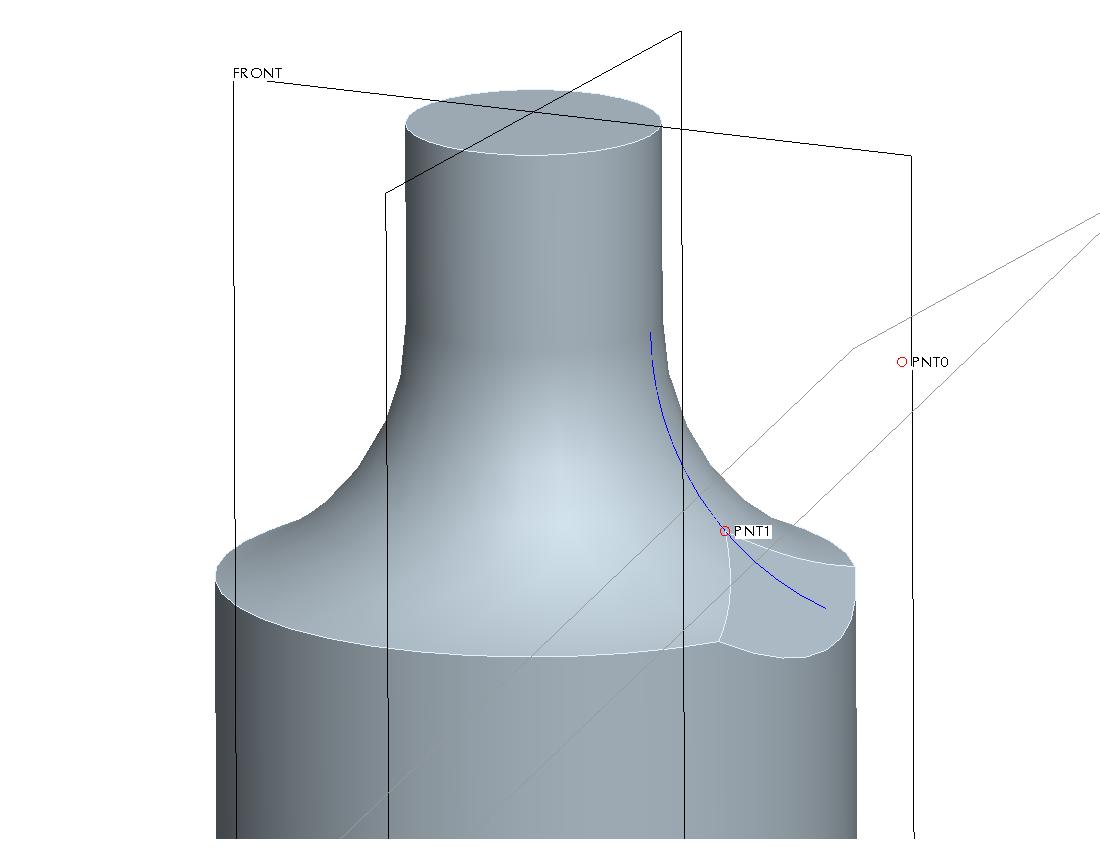
Jul 22, 2011
02:23 PM
- Mark as New
- Bookmark
- Subscribe
- Mute
- Subscribe to RSS Feed
- Permalink
- Notify Moderator
Please log in to access translation
Jul 22, 2011
02:41 PM
- Mark as New
- Bookmark
- Subscribe
- Mute
- Subscribe to RSS Feed
- Permalink
- Notify Moderator
Please log in to access translation
Jul 22, 2011
02:41 PM
Seems to be very robust! Thanks for the solution. You would still think that it should be easier than that, but this solution seems to be the most robust, workable solution.
Thanks again!
-Greg


